MD600 Series Compact AC Drive Hardware Guide-EN-B06.PDF - 第61页
Installation ‑ 60 ‑ Procedure 1. Use a Phillips screwdriver to secure the M4x12 cross recessed pan head SEMS screw (with the flat washer and spring washer) on the upper right side of the drive, as shown in ①. 2. Repeat t…

Installation
‑59‑
Table 5–4 Wiring tools for main circuit terminals
Structure
Recommended fastener Tool
T1–T2
Terminal block Cable stripper and cable
pliers
5.2 Pre-installation Inspection
Complete the following inspection items before installation.
Table 5–5 Pre-installation checklist
No. Item
Tick
1
The mechanical strength of the mounting position can bear the
weight of the device.
□
2
The environment and load-bearing capacity of the mounting
position fulfill the installation requirements.
□
3
Sufficient clearance is reserved for heat dissipation, including for
heat dissipation of other devices in the cabinet.
□
4
The mounting bracket (if needed) is made of incombustible
materials.
□
5
If the application site is exposed to metal dust, install the
equipment in an enclosed cabinet to isolate the equipment from the
metal dust. In this case, the space inside the cabinet needs to be as
large as possible.
□
6
Before installing the AC drive, install the bottom mounting bracket
in the cabinet and guide rails (optional), and prepare mounting
beams with holes reserved to fix the AC drive.
□
7
Keep combustible and explosive materials away from the
equipment.
□
5.3 Installing the AC Drive
5.3.1 Installation Method
5.3.1.1 Backplate Mounting
Backplate mounting is applicable to T1 (single-phase 200-240 V: 0.37-1.5 kW;
three-phase 380-480 V: 0.37-2.2 kW) and T2 models (single-phase 200-240 V: 2.2
kW; three-phase 380-480 V: 4-5.5 kW).
Prerequisites
Before installation, check that the installation tools and environment have been
prepared. For details, see
" Pre-installation Preparation
"
on page 56
. This section
describes quick backplate mounting steps.
Installation
‑60‑
Procedure
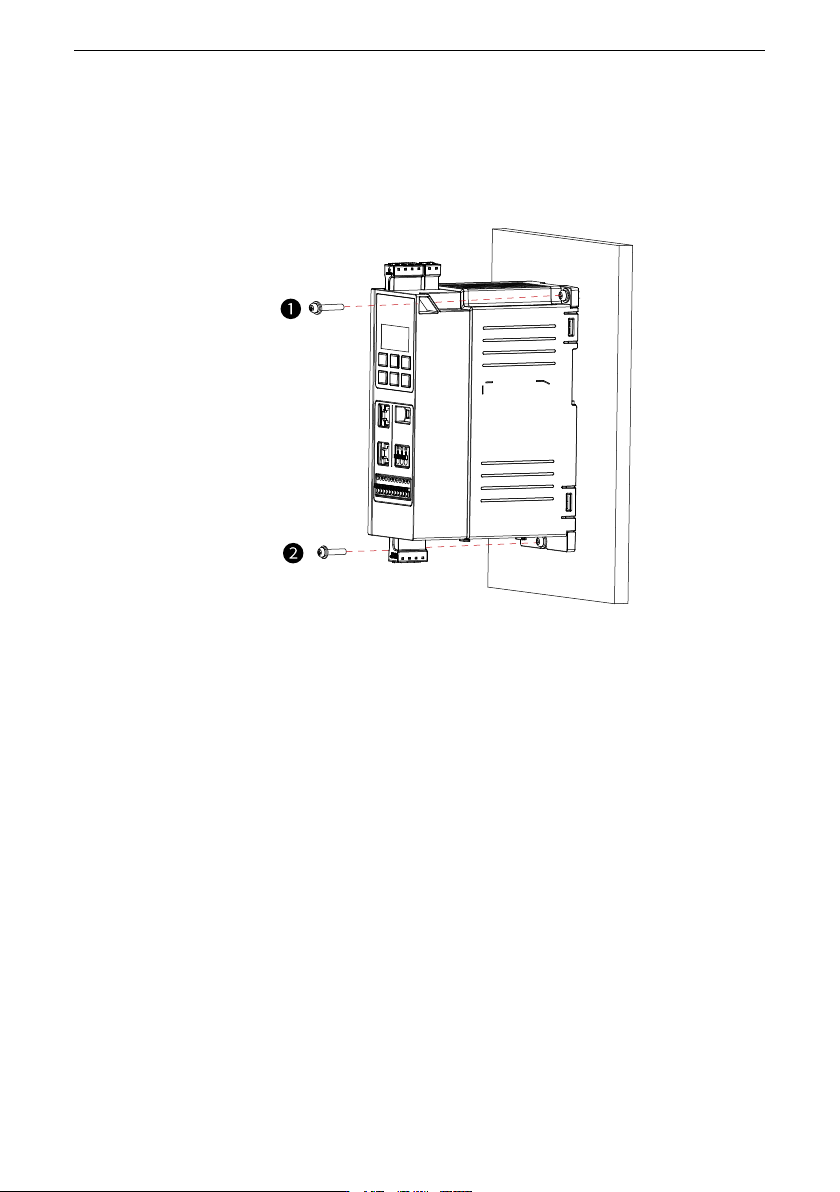
1. Use a Phillips screwdriver to secure the M4x12 cross recessed pan head SEMS
screw (with the flat washer and spring washer) on the upper right side of the
drive, as shown in ①.
2. Repeat the previous step to fix the screw below the drive, as shown in ②.
5.3.1.2 Guide Rail Mounting
Install the guide rail for T1 models (three-phase 380-480 V: 0.37-2.2 kW; single-phase
200-240 V: 0.37-1.5 kW). For T2 models (three-phase 380-480 V: 4-5.5 kW; single-phase
200-240 V: 2.2 kW), the guide rail is not required.
Prerequisites
● To install the AC drive with a guide rail, order the DIN guide rail (option). For details,
see
"12.1 List of Options
"
on page 102
.
● Before installation, check that the installation tools and environment have been
prepared. For details, see
" Pre-installation Preparation
"
on page 56
. This section
describes quick guide rail installation steps.
Procedure
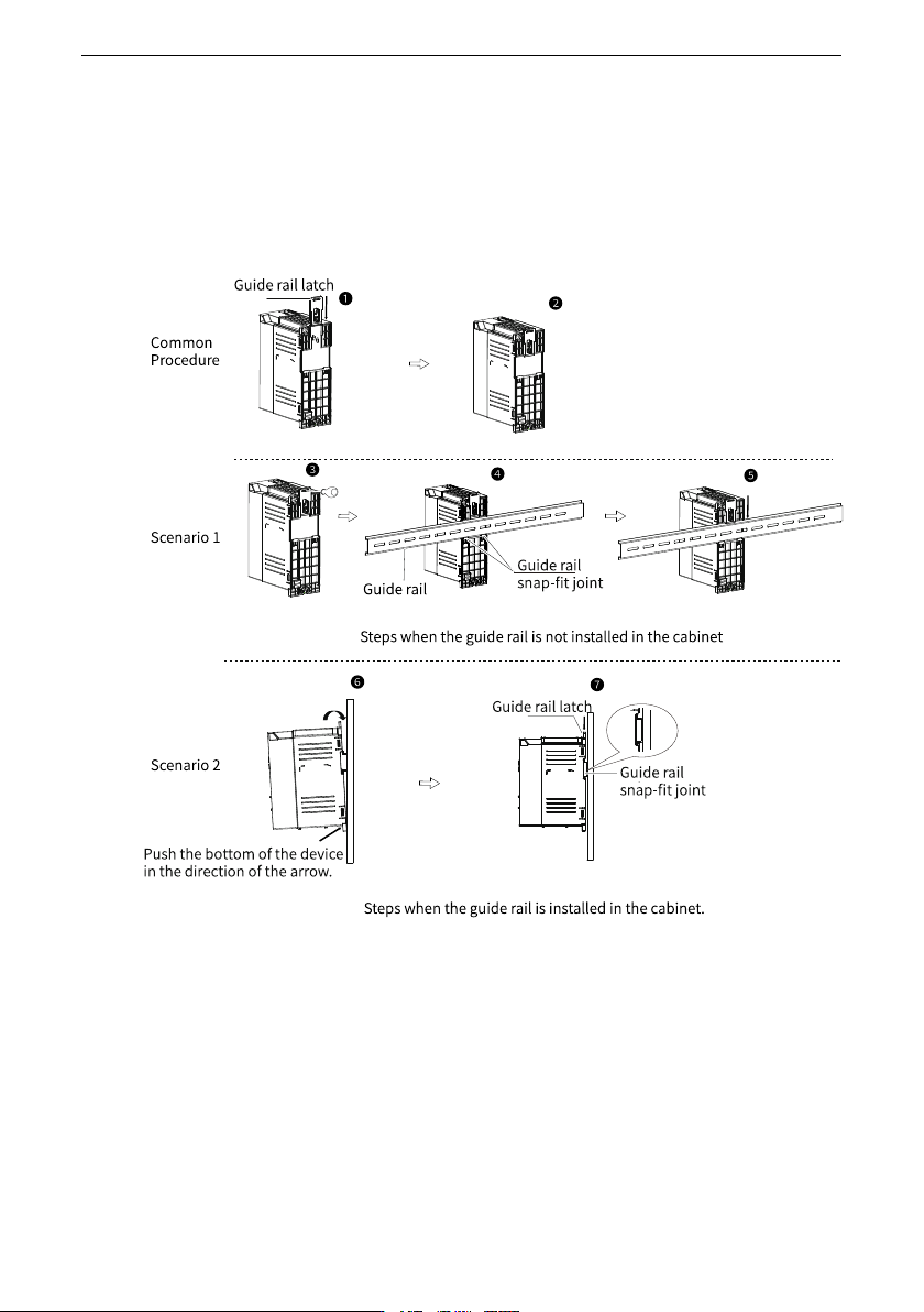
1. Insert the guide rail latch into the slot at the bottom of the drive until it clicks into place,
as shown in ①.
Figure ② shows that the guide rail is installed in place.
Scenario 1: The guide rail is not installed in the cabinet.
2. Use the straight screwdriver to pull the guide rail latch up slightly, as shown in ③.
Installation
‑61‑
3. Install the guide rail to the snap-fit joint on the drive, as shown in ④.
4. Press the guide rail latch down to the place to lock the guide rail, as shown in ⑤.
Scenario 2: The guide rail is installed in the cabinet.
5. Hold the drive at the fixing position, push the bottom of the drive in the direction of the
arrow to the place to lock it to the snap-fit joint, as shown in ⑥.
6. Press the guide rail latch down to the place to lock the guide rail, as shown in ⑦.
Figure 5‑2 Guide rail installation
5.4 Post-Installation Inspection
After installation is done, check the following items.