MD600 Series Compact AC Drive Hardware Guide-EN-B06.PDF - 第118页
Option ‑117‑ Selecting the resistance of the braking resistor The built-in braking unit of the drive processes the regenerative energy generated by the motor during deceleration. When the DC bus voltage exceeds the limit…
Option
‑116‑
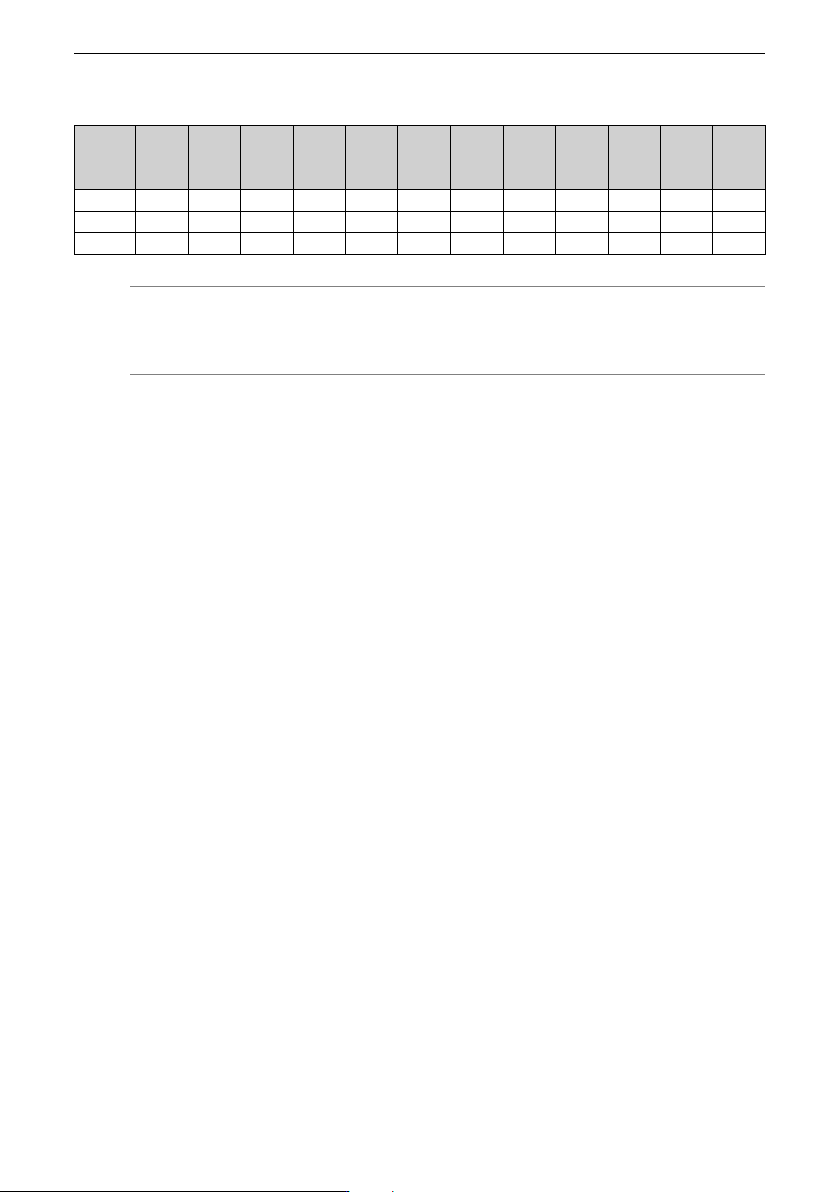
Table 12–15 Dimensions of FN3287 filters (unit: mm)
Rated
current
(A)
A B C D E F G H
J±2
K L±1 M
10 180 40 112 153 0.8 170 20 4.5 94 11 68 M5
16 200 45 112 170 0.8 185 25 5.4 102 11 76 M5
25 205 45 132 173 0.8 190 25 5.4 113 13 83 M5
Note
If you need an EMC filter of Schaffner, you can purchase it from the manufacturer.
12.7 Braking Resistor
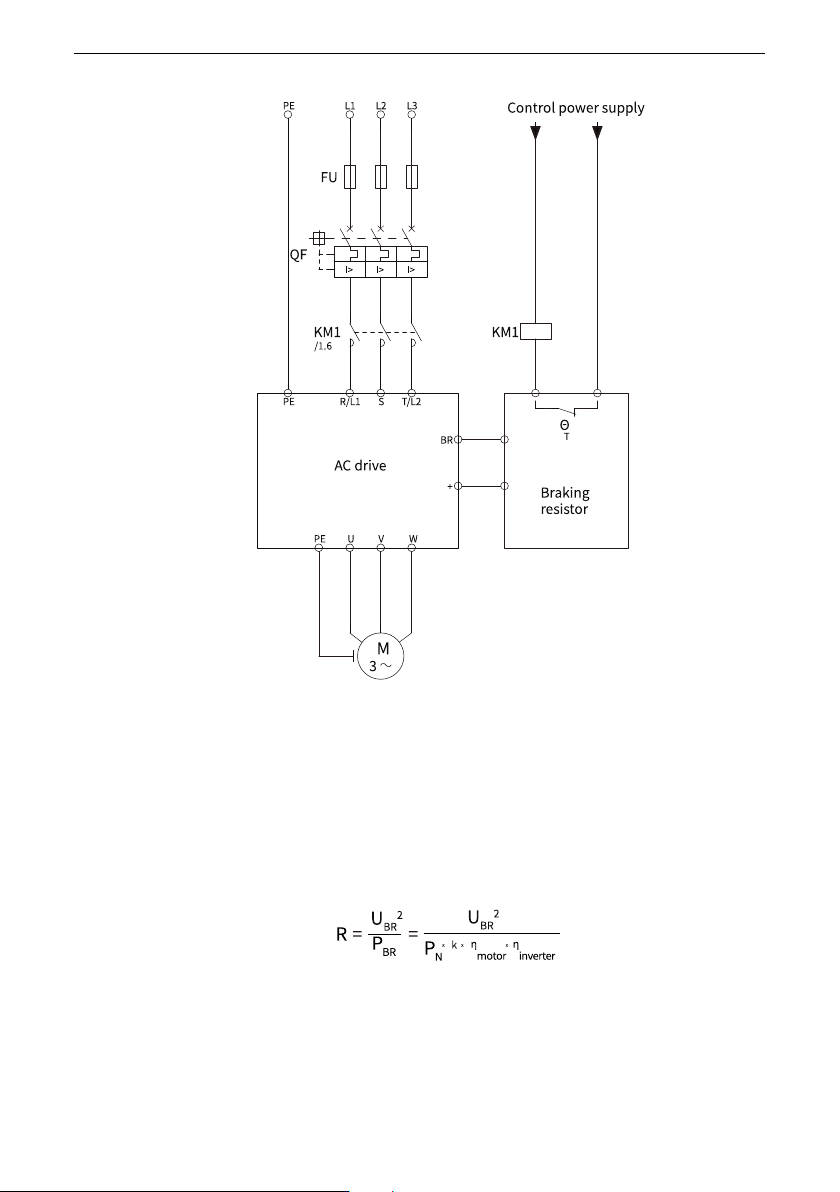
Braking resistor protection
In applications where a braking resistor is installed, it is recommended to use a resistor
with a temperature switch to ensure safety and avoid overheating and burning of the
braking resistor. Connect the temperature switch output to the electromagnetic contactor
control circuit on the front end of the drive (as shown in the following figure) to
implement the interlock protection function. When the resistor overheats, a tripping fault
occurs, avoiding the resistor to be burned.
Option
‑117‑
Selecting the resistance of the braking resistor
The built-in braking unit of the drive processes the regenerative energy generated by the
motor during deceleration. When the DC bus voltage exceeds the limit set by the
software, the braking unit automatically turns on and connects the braking resistor to the
DC bus. The braking resistor consumes the regenerative energy to keep the bus voltage
within the safe range. The braking resistor is disconnected until the bus voltage drops
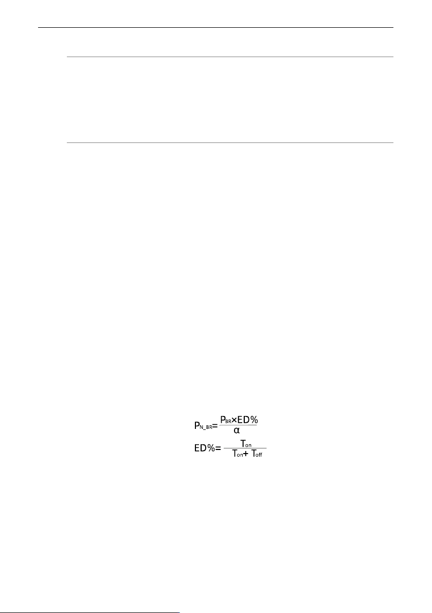
below a certain range. The resistance of the braking resistor is calculated based on the
following formula.
Option
‑118‑
Note
When the braking power is fed back from the motor to the U/V/W cable, and then fed
back from the U/V/W cable to the DC bus of the drive, the braking power will be derated
by the motor efficiency and the drive efficiency, respectively. Therefore, the braking
power actually consumed by the braking resistor will be lower. The conversion coefficient
is roughly estimated to be from 0.8 to 0.9.
R: Resistance of the braking resistor
U
BR
: Braking start voltage of the AC drive. The default braking start voltage of three-
phase 380 V to 480 V models and single-phase 200 V to 240 V models are 760 V and 370
V, respectively, which can be changed via parameters.
P
BR
: Braking power that needs to be consumed by the braking resistor on the DC bus of
the drive
P
n
: Rated power of the drive
k: Multiple of the braking torque to the rated torque, which is set to 1.25 generally The k
value can be adjusted as needed.
ƞ
motor
: Motor efficiency, which is generally set to 0.85 set based on the actual motor
efficiency. It can also be estimated based on the efficiency of the four-pole motor energy
efficiency class IE3 specified in the IEC 60034-30-2 standard.
ƞ
inverter
: Between 0.9 to 0.98 generally
Selecting the power of the braking resistor
In theory, the power of the braking resistor is the same as the average power
consumption of the braking resistor on the bus. However, given that the braking resistor
is naturally ventilated in the power distribution cabinet, power derating must be applied.
Assume that the derating coefficient is α. You can select the rated power of the braking
resistor according to the following formula: