MD600 Series Compact AC Drive Hardware Guide-EN-B06.PDF - 第26页
Product Information ‑25‑ No. Name Remarks 7 Relay terminal (CN3) Relay output terminal 8 R (L1)/S/T (L2)/PE input terminals It is used to connect three-phase/single-phase AC input power supplies. R/S/T terminals are used…
Product Information
‑24‑
Table 2–2 Relationship between the product model and structure (CAN version)
Struc
ture
Three-phase 380 V to 480 V Single-phase 200 V to 240 V
Power (kW)
Product model
Power (kW)
Product model
T1 0.37
MD600A-4T1R6(B)
0.37
MD600A-2S2R8(B)
0.75
MD600A-4T2R3(B)
0.75
MD600A-2S4R6(B)
1.5
MD600A-4T4R8(B)
1.5
MD600A-2S7R5(B)
2.2
MD600A-4T5R5(B)
T2 4
MD600A-4T9R5(B)
2.2
MD600A-2S010(B)
5.5
MD600A‑4T013(B)
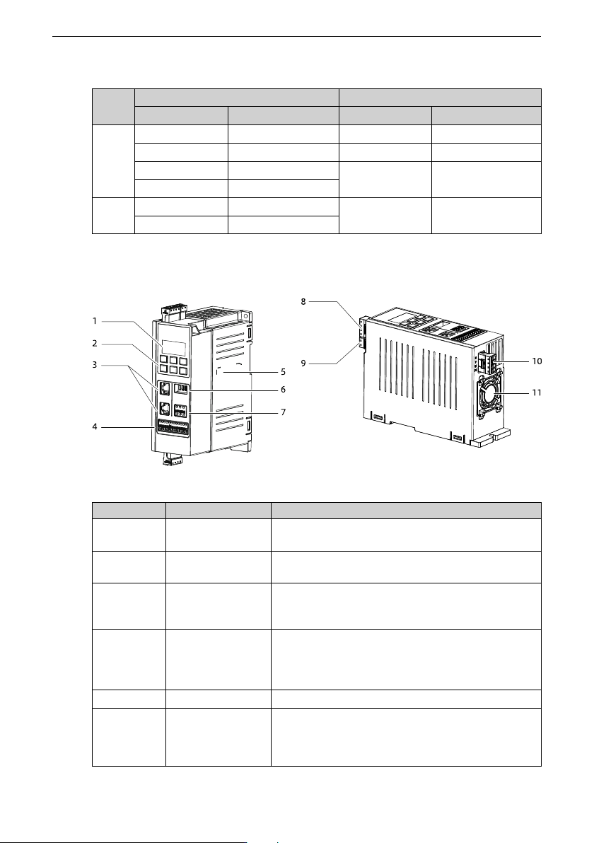
2.4 Components
Figure 2‑2 Components
No. Name
Remarks
1
LED display on the
operating panel
It displays the axis number, status, unit, and data.
2
Keys on the
operating panel
It is used for operations through the operating
panel.
3
Communication
terminal (CN1/
CN2)
-
4
Control circuit
terminal (CN4)
It integrates the Modbus RTU communication,
analog input, analog output, digital input, digital
output, 24 V power supply output, and 10 V power
supply output signals.
5
Product nameplate It displays the product information.
6
DIP switch for
termination
resistor
DIP switch for the Modbus communication
termination resistor in CN1
DIP switch for the CAN communication termination
resistor in CN1 and CN2
Product Information
‑25‑
No. Name
Remarks
7
Relay terminal
(CN3)
Relay output terminal
8
R (L1)/S/T (L2)/PE
input terminals
It is used to connect three-phase/single-phase AC
input power supplies. R/S/T terminals are used to
connect the three-phase power supply. L1/L2
terminals are used to connect the single-phase
power supply, and PE is the protective earthing
terminal.
9
Braking terminal It is used to connect the braking resistor.
10
U/V/W/PE output
terminals
U/V/W terminals are used to connect the three-
phase motor, and PE is the protective earthing
terminal.
11
Cooling fan It is used for heat dissipation.
System Connection
‑26‑
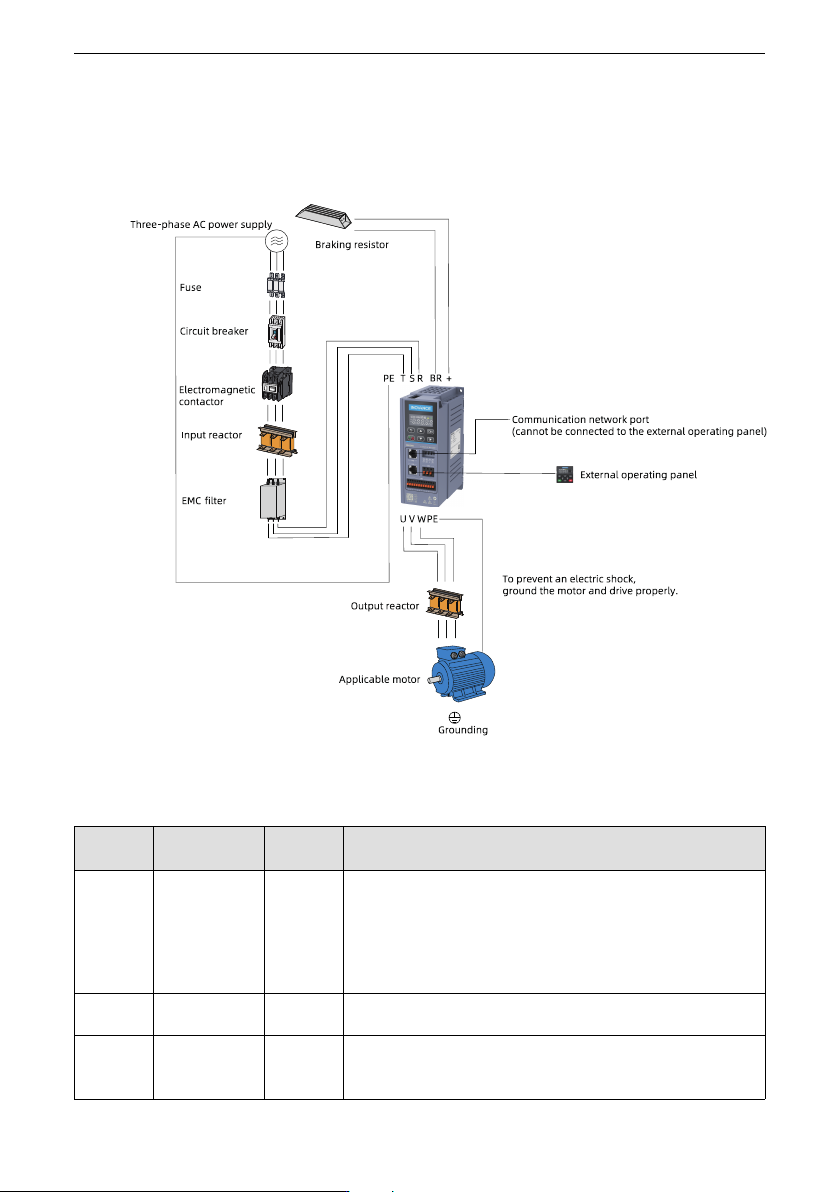
3 System Connection
When using the AC drive to drive an asynchronous motor, a variety of electrical
components must be installed on both input and output sides to ensure system safety
and stability. The following figure shows the system composition.
Figure 3‑1 System Connection
Table 3–1 Description of electrical peripherals
Component
Installation
position
Applicable
model
Function overview
Circuit
breaker
Input side of the
drive
All models Installed between the power supply and input side of the drive.
Short circuit breaker: Cuts off the power supply when overcurrent occurs
on downstream devices to prevent accidents.
Residual current device (RCD): The drive may generate high-frequency
leakage current during running. To prevent electric shock which may
cause a fire, select a proper RCD based on actual applications.
Fuse Input side of the
drive
All models Provides protection in case of short circuit to protect downstream
semiconductors.
Electromag
netic
contactor
Input side of the
drive
All models It is used to connect to or cut off the power supply of the AC drive. Do
not use the contactor to power on or off the drive frequently (interval: at
least one hour) or use the contactor to directly start the drive.