MD600 Series Compact AC Drive Hardware Guide-EN-B06.PDF - 第48页
Electrical Design ‑47‑ Figure 4‑12 Routing different types of signal cables ● Routing of multi-conductor cables Use one multi-conductor cable to transmit one type of signals. If you need to use one multi-conductor cable …
Electrical Design
‑46‑
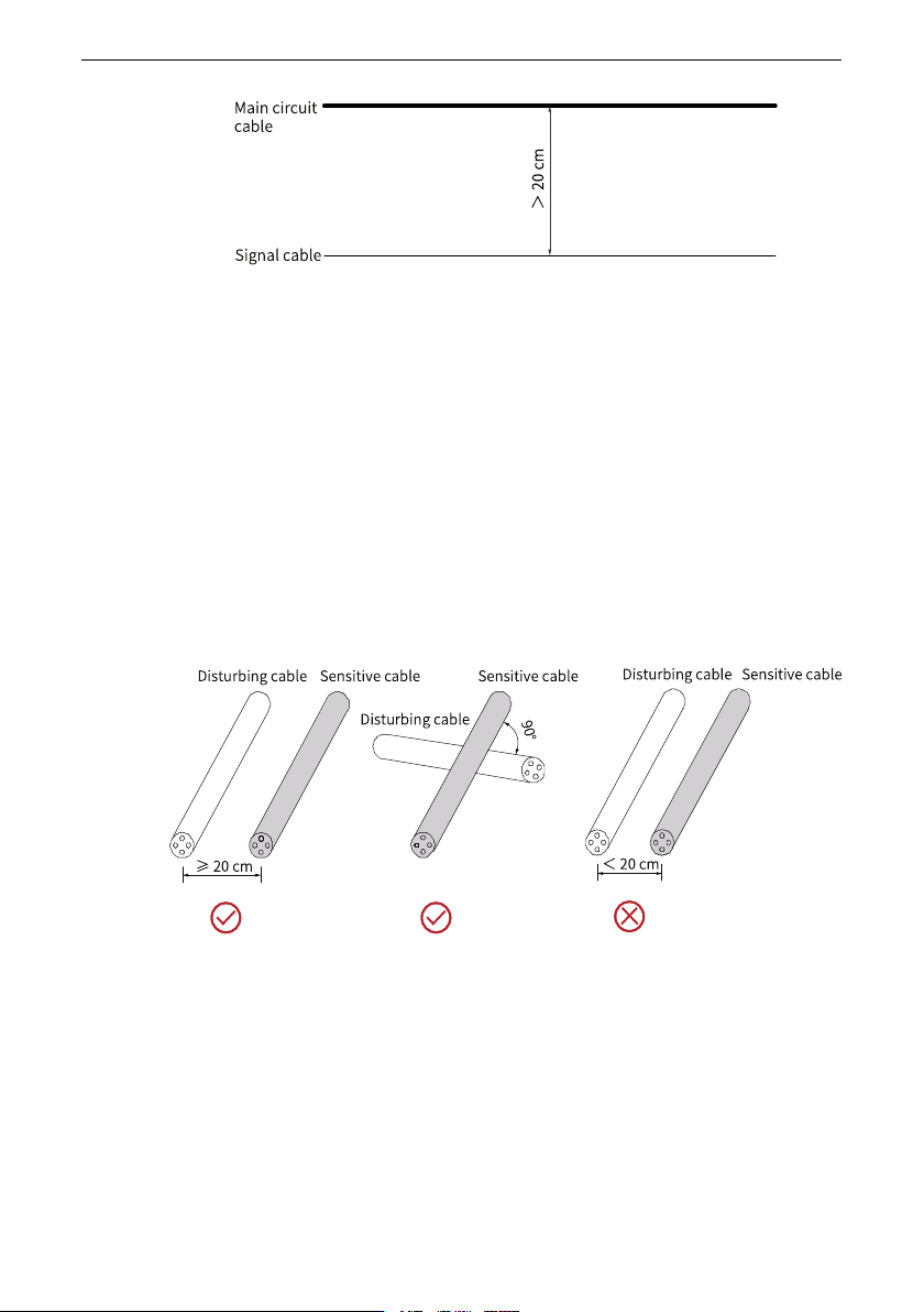
Figure 4‑10 Cabling diagram
● Requirements on cabling I/O signal cables
I/O signals include analog input (AI), analog output (AO), digital input (DI), digital
output (DO) and relay output signals. To avoid interference to the I/O signals,
separate the I/O signal cables at least 20 cm from the main circuit cables (R/S/T
cables and U/V/W cables) and other power cables or power supply cables.
Routing recommendations
● Routing of disturbing cables and sensitive cables
During routing, route cables that transmit different types of signals through different
routes. Separate the disturbing cables from sensitive cables by a distance of 20 cm
wherever possible. When two types of cables must be intersected, the intersection
angle must be 90 degrees to avoid interference, as shown in the following figure.
Figure 4‑11 Routing of disturbing cables and sensitive cables
● Routing of cables transmitting different types of signals
Route cables that transmit different types of signals through different routes and
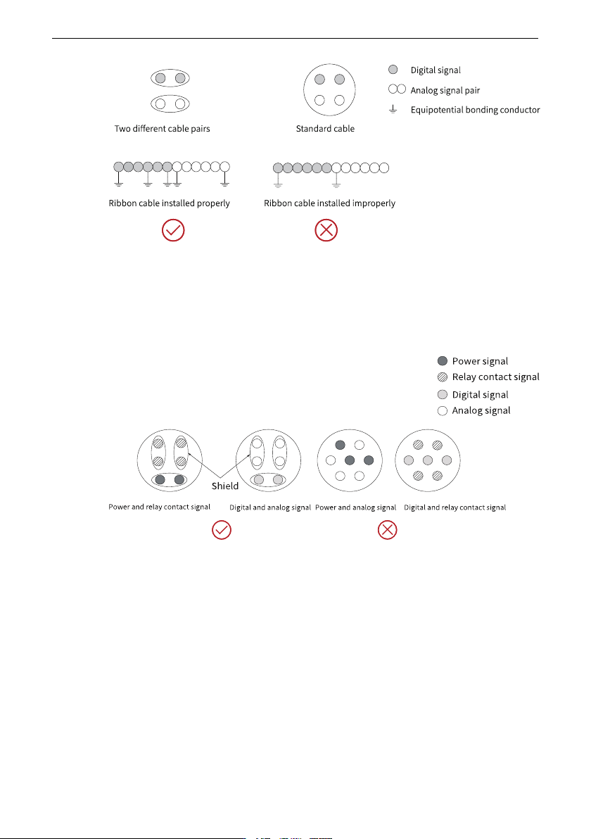
separate them with equipotential signal cables. When routing cables that transmit the
same type of signals, the equipotential signal cable stays in the outer layer and
equipotential signals should stay in the middle if possible, as shown in the following
figure.
Electrical Design
‑47‑
Figure 4‑12 Routing different types of signal cables
● Routing of multi-conductor cables
Use one multi-conductor cable to transmit one type of signals. If you need to use one
multi-conductor cable to transmit different types of signals, isolate the conductors
that transmit one type of signals, as shown in the following figure.
Figure 4‑13 Routing of multi-conductor cables
If certain conductors in a multi-conductor cable are reserved or unused, connect these
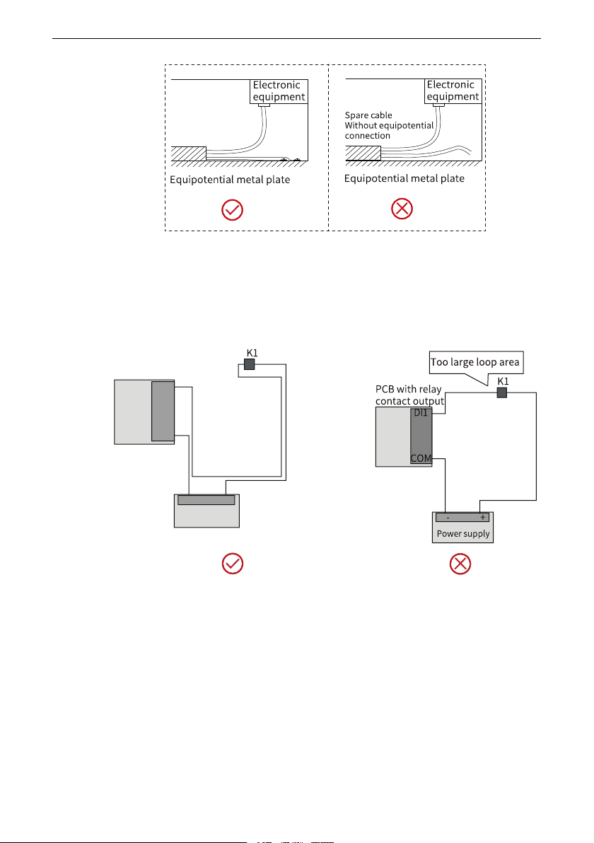
conductors to the equipotential bonding point, as shown below.
Electrical Design
‑48‑
Figure 4‑14 Handling of unused conductors in a multi-conductor cable
● Requirements on the wiring loop area
For cables that transmit low-level sensor signals and shared cables that transmit
relay signals, lay them close to each other to avoid a large loop area. Use twisted pair
cables for analog signals. Lay digital signal cables close to each other.
Figure 4‑15 Recommended wiring loop area
● Laying multiple types of cables
For cables of different types, route the cables along the equipotential metal plate. To
enhance the internal EMC performance, separate different types of cables or separate
cables with metal separators (recommended) in the same metal (zinc‑iron or stainless
steel) duct, as shown below.