MD600 Series Compact AC Drive Hardware Guide-EN-B06.PDF - 第74页
Wiring ‑73‑ Figure 6‑7 Wiring of AI terminals To select the current input mode for AI1, set S3 to ON. In this case, the input resistance is 500 Ω. The wiring is as follows. Figure 6‑8 Wiring of AI1 in the current input m…
Wiring
‑72‑
Table 6–4 DIP switch definitions
Name Function
S1 ON: Termination resistor connected for RS485/CAN communication
OFF: Termination resistor disconnected for RS485/CAN communication
S2 ON: Termination resistor connected for RS485/CAN communication
OFF: Termination resistor disconnected for RS485/CAN communication
S3 ON: AI1 supports the current input mode (impedance: 500 Ω).
OFF: AI1 supports the voltage input mode.
S4 NC: OP unconnected
24: OP is connected to the internal 24 V power supply.
Note
● By default, the DIP switch is in the OFF position.
● To connect the termination resistor, S1 and S2 must be set to ON at the same
time.
6.3.2 Wiring Descriptions of Control Circuit Terminals
Precautions
I/O signals include analog input (AI), analog output (AO), digital input (DI), digital output
(DO) and relay output signals. To avoid interference to the I/O signals, separate the I/O
signal cables at least 20 cm away from the main circuit cables (R/S/T cables and U/V/W
cables) and other power cables or power supply cables.
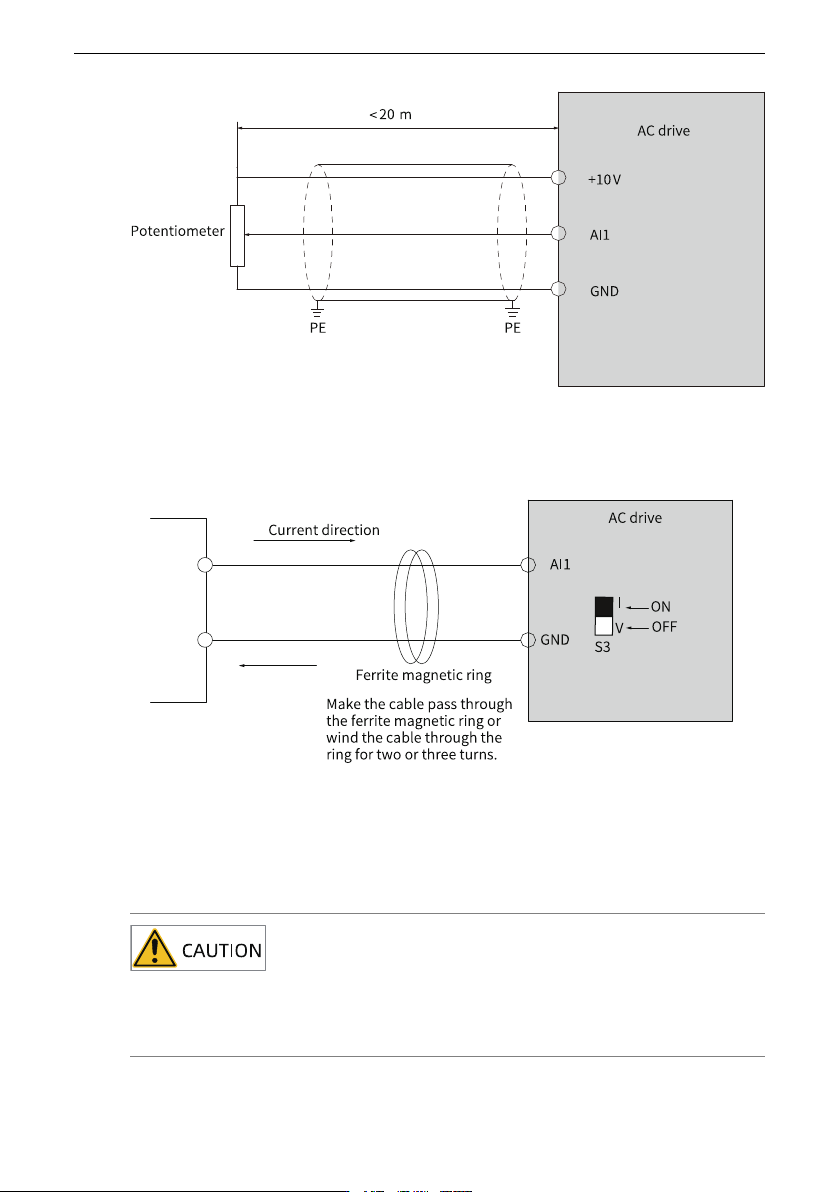
Wiring AI1
Weak analog signals are easy to suffer external interference. Therefore, route the analog
cable away from the interference source and keep the cable length as short as possible
(no longer than 20 m). In applications where the analog signal suffers severe
interference, install a filter capacitor or ferrite core at the analog signal source, as shown
in
"Figure 6–7 Wiring of AI terminals
"
on page 73
.
Wiring
‑73‑
Figure 6‑7 Wiring of AI terminals
To select the current input mode for AI1, set S3 to ON. In this case, the input resistance is
500 Ω. The wiring is as follows.
Figure 6‑8 Wiring of AI1 in the current input mode
Wiring DI1 to DI5
When the OP terminal is connected to the internal 24 V (DIP switch S4 set to 24V), do not
short the COM and OP terminals. Otherwise, the internal 24 V power supply will be
damaged.
Wiring
‑74‑
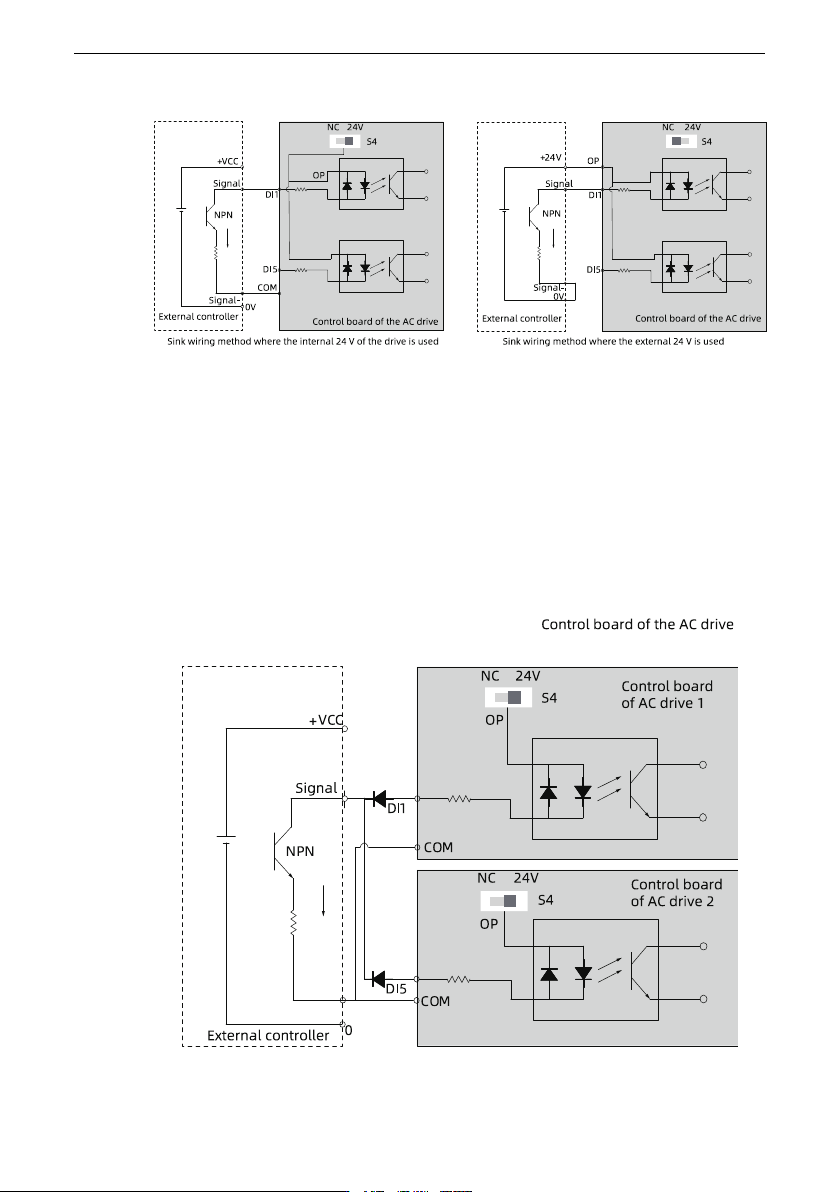
● Sink wiring
Figure 6‑9 Sink wiring
To use the internal 24 V power supply of the drive, which is the most commonly wiring
method, set the DIP switch S4 to 24V (short the OP and 24V terminals), and connect
the COM terminal of the drive to the 0V terminal of the external controller.
In the mode, the DIs of different AC drives cannot be connected in parallel. Otherwise,
the DI may malfunction. If DIs of different AC drives must be connected in parallel,
connect the anode of a diode to the DI in series and the diode needs to satisfy the
requirement: IF > 40 mA and VR > 40 V, as shown in
"Figure 6–10 Parallel connection
of DIs of different AC drives in sink wiring mode
"
on page 74
.
Figure 6‑10 Parallel connection of DIs of different AC drives in sink wiring mode