MD600 Series Compact AC Drive Hardware Guide-EN-B06.PDF - 第59页
Installation ‑ 58 ‑ 5.1.3 Installation Tools Mechanical Installation Tools For details about the tools, see "Table 5–2 Tools for mechanical installation " on page 58 . Table 5–2 Tools for mechanical installatio…
Installation
‑57‑
Environment Conditions
Altitude
● 1000 m and below: Derating is not needed.
● Derating is needed for altitudes above 1000 m (derate 1% for
every additional 100 m).
If the altitude is higher than 2000 m, consult your Inovance
agent or sales personnel.
Vibration resistance
● Operation scenario: Tested according to IEC 60068-2-6.
Amplitude at 5 Hz to 8.4 Hz: 3.5 mm; acceleration at 8.4 Hz to
200 Hz: 1 g; 10 cycles/axis
● Transportation scenario: Tested according to IEC 60068-2-64.
Power spectrum density at 5 Hz to 100 Hz: 0.01 g²/Hz; power
spectrum density at 200 Hz: 0.001 g²/Hz; Grms: 1.14 g
Shock Operating/Transport environment: Tested according to IEC
60068-2-27. Acceleration: 15 g; pulse width; 11 ms; 18 times in
directions of three axes
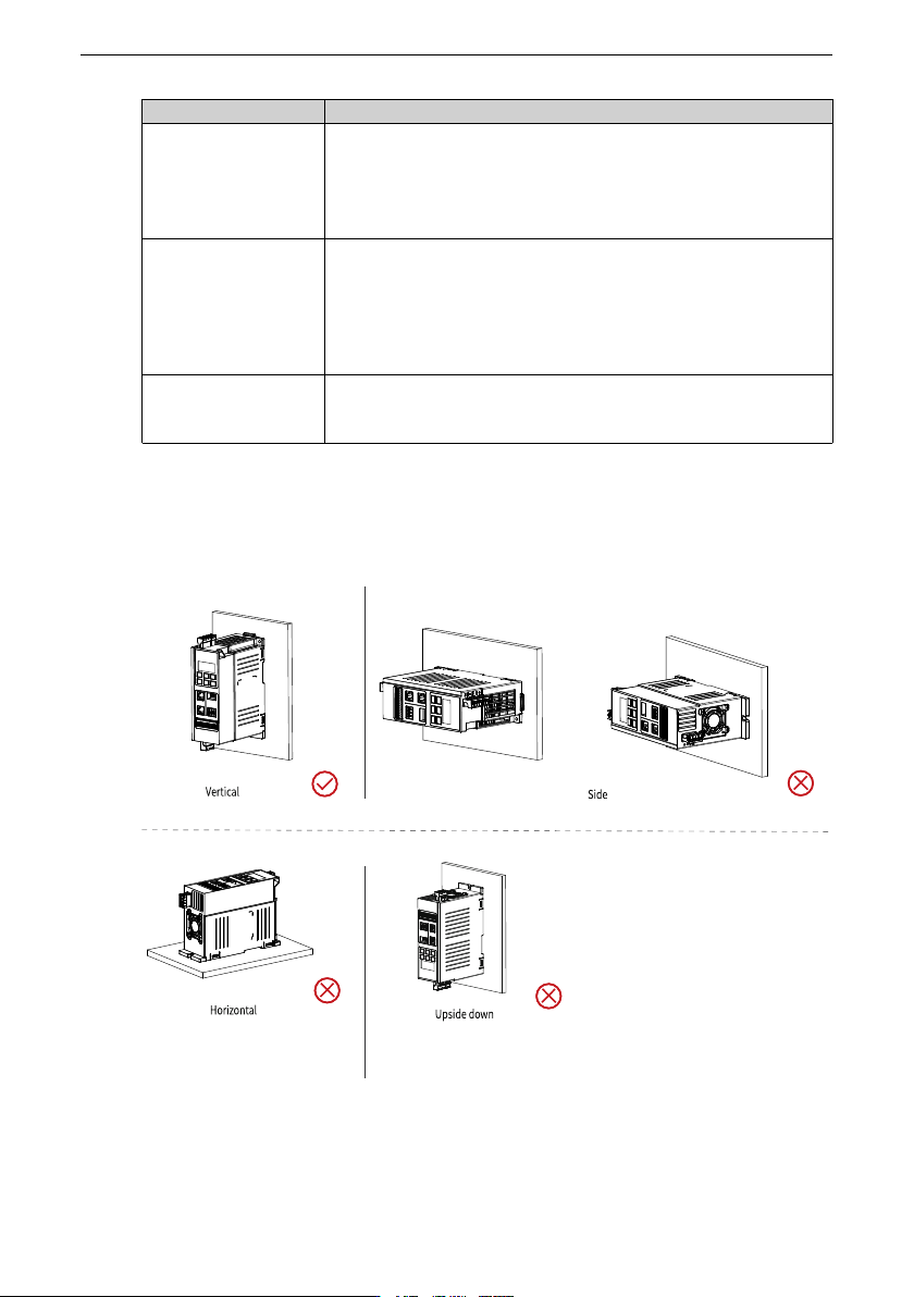
5.1.2 Installation Direction
Install the AC drive upright, as shown in the following figure. Do not lie the AC drive on its
back or side, or install it in the upside-down direction.
Figure 5‑1 Installation direction
Installation
‑58‑
5.1.3 Installation Tools
Mechanical Installation Tools
For details about the tools, see
"Table 5–2 Tools for mechanical installation
"
on page 58
.
Table 5–2 Tools for mechanical installation
Tool name
Description
Electric drill and appropriate drilling bits It is used to drill mounting holes on the
mounting surface.
Phillips screwdriver and straight
screwdriver (2.5 mm to 6 mm)
Used to tighten or loosen screws.
Caliper or tape measure Used to measure the installation
dimensions of the equipment.
Gloves Used to prevent static electricity during
installation.
Screw
It is used to fix the equipment to the
mounting surface.
Rail bracket It is used to fix the drive onto the rail
bracket.
Screw
For screw specifications and quantity, see
"Table 5–3 Specifications and quantity of
screws
"
on page 58
.
Table 5–3 Specifications and quantity of screws
Installa
tion
method
Screw
Specification
Recommended
tightening torque
of the screw
(Unit: kgf.cm)
Quantity
(Unit: PCS)
Description
Back
plate
Mount
ing
M4x12 cross
recessed pan
head SEMS
screws (with flat
washer and
spring washer)
12 2
Used to fix the drive
onto the wall
Tools for Wiring
When wiring the main circuit terminal, select an appropriate installation tool based on
the terminal size.
Installation
‑59‑
Table 5–4 Wiring tools for main circuit terminals
Structure
Recommended fastener Tool
T1–T2
Terminal block Cable stripper and cable
pliers
5.2 Pre-installation Inspection
Complete the following inspection items before installation.
Table 5–5 Pre-installation checklist
No. Item
Tick
1
The mechanical strength of the mounting position can bear the
weight of the device.
□
2
The environment and load-bearing capacity of the mounting
position fulfill the installation requirements.
□
3
Sufficient clearance is reserved for heat dissipation, including for
heat dissipation of other devices in the cabinet.
□
4
The mounting bracket (if needed) is made of incombustible
materials.
□
5
If the application site is exposed to metal dust, install the
equipment in an enclosed cabinet to isolate the equipment from the
metal dust. In this case, the space inside the cabinet needs to be as
large as possible.
□
6
Before installing the AC drive, install the bottom mounting bracket
in the cabinet and guide rails (optional), and prepare mounting
beams with holes reserved to fix the AC drive.
□
7
Keep combustible and explosive materials away from the
equipment.
□
5.3 Installing the AC Drive
5.3.1 Installation Method
5.3.1.1 Backplate Mounting
Backplate mounting is applicable to T1 (single-phase 200-240 V: 0.37-1.5 kW;
three-phase 380-480 V: 0.37-2.2 kW) and T2 models (single-phase 200-240 V: 2.2
kW; three-phase 380-480 V: 4-5.5 kW).
Prerequisites
Before installation, check that the installation tools and environment have been
prepared. For details, see
" Pre-installation Preparation
"
on page 56
. This section
describes quick backplate mounting steps.