MD600 Series Compact AC Drive Hardware Guide-EN-B06.PDF - 第123页
Option ‑ 122 ‑ Recommended braking resistor power under different braking conditions The braking resistor power in the above table is recommended under the condition of 125% braking torque, 10s braking on-time (Ton), and…
Option
‑121‑
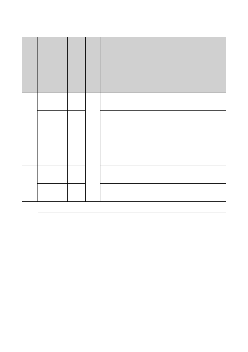
Table 12–17 Selection of braking resistors (three-phase 380 V to 480 V)
Struc
ture
Drive model
Applica
ble
motor
(kW)
Brak
ing
unit
Specifications of
the
recommended
braking resistor
(125% braking
torque, 10% ED,
max. 10s)
Actual braking resistor selection (Inovance
model)
Mini
mum
baking
resist
ance
(Ω)
Braking resistor
model
Resist
ance of
a
single
resistor
(Ω)
Power
of a
single
motor
(W)
Num
ber of
paral
lel
resis
tors
(PCS)
T1
MD600S/A-
4T1R6(B)
0.37
Built-
in unit
(op
tional)
60 W/1560 Ω
RXLG-50W-
1560RJ-XZ1000-
OE-B
1560 50 1 69
MD600S/A-
4T2R3(B)
0.75 110 W/770 Ω
RXLG-100W-
770RJ-XZ1000-
OE-B
770 100 1 69
MD600S/A-
4T4R8(B)
1.5 230 W/380 Ω
RXLG-200W-
380RJ-XZ1000-
OE-B
380 200 1 69
MD600S/A-
4T5R5(B)
2.2 330 W/260 Ω
RXLG-300W-
260RJ-XZ1000-
OE-B
260 300 1 69
T2
MD600S/A-
4T9R5(B)
4 600 W/140 Ω
RXLG-600W-
140RJ-XZ1000-
OE-B
140 600 1 41
MD600S/
A‑4T013(B)
5.5 830 W/100 Ω
RXLG-800W-
100RJ-XZ1000-
OE-B
100 800 1 41
Note
● The braking resistance in the above table is under the condition of 125% braking
torque, 10s braking on-time (Ton), and 10% braking duty cycle (ED%).
● For single-phase 200 V to 240 V, the default initial braking voltage of the built-in
braking unit is 370 V. For three-phase 380 V to 480 V, the default initial braking
voltage of the built-in braking unit is 760 V.
● The data in the preceding table is only for reference. You can select the
resistance and power of the braking resistor as required. (Note that the
resistance cannot be lower than the recommended minimum value, whereas the
power can exceed or be equal to the recommended value.) Select the braking
resistor based on the generation power of the motor in the actual system,
system inertia, deceleration time, and potential energy load.
● For systems featuring large inertia frequent braking and requiring short
deceleration time, select a braking resistor with high power and low resistance.
Option
‑122‑
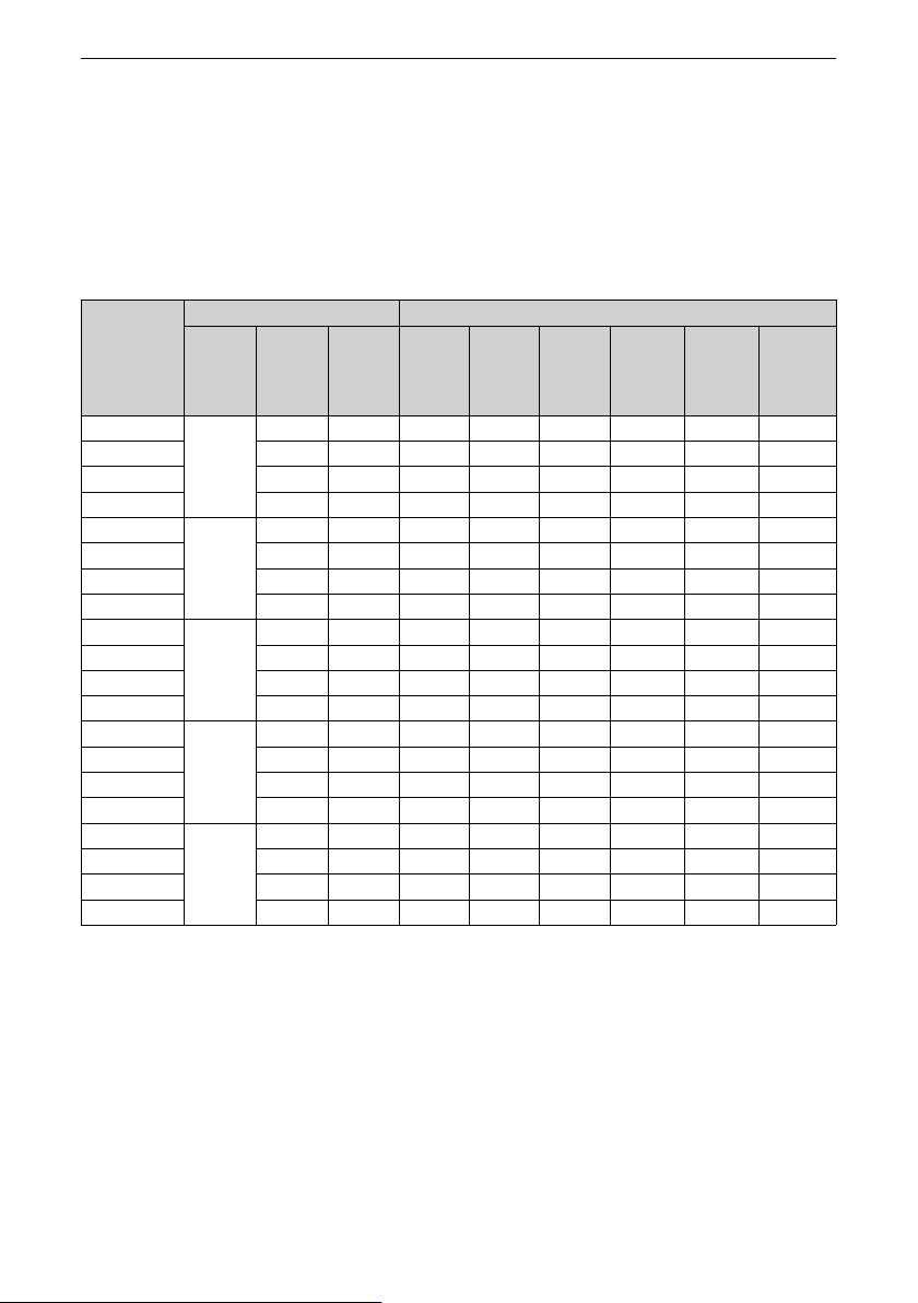
Recommended braking resistor power under different braking conditions
The braking resistor power in the above table is recommended under the condition of
125% braking torque, 10s braking on-time (Ton), and 10% braking duty cycle (ED%).
However, in actual applications, braking conditions vary and cannot be fully summarized
by a single typical condition. The following lists the recommended braking resistor power
for different braking duty cycles and different braking on-time (Ton) at 125% braking
torque for your reference.
Braking
condition
Braking condition Braking resistor power (at 125% braking torque) (kW)
Braking
on-time
Ton/s
Braking
off-time
Toff/s
Braking
duty
cycle
ED%
0.37 0.75 1.5 2.2 4 5.5
3s, 10% ED 3 27 10% 40 90 170 250 460 630
3s, 15% ED 17 15% 60 120 240 360 650 900
3s, 25% ED 9 25% 100 200 390 570 1050 1440
3s, 40% ED 4.5 40% 150 310 610 900 1640 2250
10s, 10% ED 10 90 10% 60 110 230 330 600 830
10s, 15% ED 56.7 15% 70 150 290 430 780 1080
10s, 25% ED 30 25% 110 220 430 640 1150 1590
10s, 40% ED 15 40% 160 320 650 950 1720 2370
20s, 10% ED 20 180 10% 80 160 310 460 840 1150
20s, 15% ED 113.3 15% 90 180 370 540 980 1350
20s, 25% ED 60 25% 120 250 490 720 1320 1810
20s, 40% ED 30 40% 170 350 690 1010 1840 2530
30s, 10% ED 30 270 10% 100 200 410 600 1090 1500
30s, 15% ED 170 15% 110 220 450 660 1200 1650
30s, 25% ED 90 25% 140 280 560 820 1480 2040
30s, 40% ED 45 40% 180 370 740 1080 1960 2700
60s, 10% ED 60 540 10% 170 340 680 1000 1810 2490
60s, 15% ED 340 15% 170 340 690 1010 1840 2530
60s, 25% ED 180 25% 180 370 740 1090 1980 2730
60s, 40% ED 90 40% 210 440 870 1280 2320 3190

Option
‑123‑
Note
1. The thermal time constant τ of the braking resistor must be larger than or equal to
100s.
2. The recommended power of the braking resistor in the preceding table is based on the
assumption that the braking torque is 125%. If Ton and ED% remain unchanged but the
braking torque changes, the power of the braking resistor changes linearly with the
braking torque. For example, the recommended power of the braking resistor for a 5.5
kW AC drive under the condition of "braking torque 125%, ED 10%, and 10s" is 830 W. If
the actual braking torque is 150% (1.2 times the braking torque 125%), the
recommended power of the braking resistor under the condition of "braking torque
150%, ED 10%, 10s" is 996 W (830 W x 1.2).
3. The temperature rise of the braking resistor varies with different heat dissipation
conditions. Therefore, the heat dissipation conditions of the resistor can also affect the
power selection of the braking resistor.
12.8 Ferrite Ring and Ferrite Clamp
Model selection
The magnetic ring can be used on the input or output side of the AC drive. Install it as
close to the AC drive as possible. When installed on the input side, the ferrite ring can be
used to suppress the noise in the input power supply system of the drive. When installed
on the output side, the magnetic ring can suppress interference generated by the AC
drive to external devices and reduce the bearing current.
In applications with leakage current and signal cable interference, install a magnetic ring
or a ferrite clamp.
● The amorphous magnetic ring has a high magnetic conductivity when the frequency
is within 1 MHz and can efficiently suppress interference of the servo drive at a high
cost.
● Ferrite clamp: featuring high permeability when the frequency is above 1 MHz and
excellent suppression performance on interference generated by low-power drives
and signal cables
DY644020H, DY805020H, and DY1207030H are all amorphous magnetic rings.