MD600 Series Compact AC Drive Hardware Guide-EN-B06.PDF - 第41页
Electrical Design ‑ 40 ‑ Table 4–9 Minimum ventilation area of the cabinet air inlet (three-phase 380 V to 480 V) Structure Power (kW) Quantity Min. Ventilation Area of Air Inlet for Direct‑Ventilation Cabinet (cm 2 ) T1…
Electrical Design
‑39‑
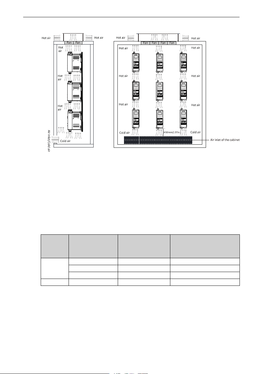
Figure 4‑8 Position of the cabinet air inlet
4.5.2.1.2 Air Outlet and Inlet
Air inlet
The effective area of the air outlet is the actual ventilation area instead of the gross
opening area. The following table describes the minimum ventilation area of the cabinet
air inlet after the drive is installed in the cabinet.
Table 4–8 Minimum ventilation area of the cabinet air inlet (single-phase 200 V to 240 V)
Structure
Power (kW) Quantity
Min. Ventilation Area of Air
Inlet for Direct‑Ventilation
Cabinet (cm
2
)
T1
0.37 1 20.5
0.75 1 16.2
1.5 1 16.2
T2 2.2 1 22
Electrical Design
‑40‑
Table 4–9 Minimum ventilation area of the cabinet air inlet (three-phase 380 V to 480 V)
Structure
Power (kW) Quantity
Min. Ventilation Area of Air
Inlet for Direct‑Ventilation
Cabinet (cm
2
)
T1
0.37 1 20.5
0.75 1 20.5
1.5 1 16.2
2.2 1 16.2
T2
4 1 22
5.5 1 22
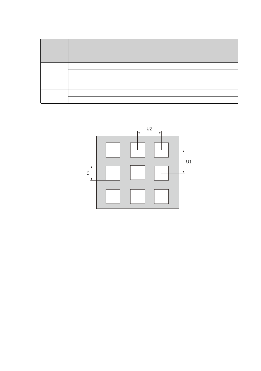
For example, on the plate shown in the following figure, the size of each hole is C x C,
and there are 9 holes. Therefore, the ventilation area of the air outlet is 9 x C x C.
The preceding tables apply only to a single product. For a cabinet containing multiple
products, calculate the total ventilation area by adding the ventilation area of each
product.
For example, a cabinet contains the following products:
T1 model (single-phase 0.37 kW) + T1 model (single-phase 1.5 kW) + T2 model (single-
phase 2.2 kW) + T1 model (three-phase 0.75 kW) + T1 model (three-phase 2.2 kW) + T2
model (three-phase 4 kW). Therefore, the minimum ventilation area of the cabinet air
inlet should be 20.5 + 16.2 + 22 + 20.5 + 16.2 + 22 = 117.4 cm
2
.
For air inlets installed with a filtering net, the air inlet resistance increases substantially.
In this case, the minimum ventilation area of the air inlet must be increased to 1.2 to 1.5
times the value listed in the preceding table. The ventilation area in the preceding tables
refers to the actual through-hole area of the opening. The ventilation area is calculated
by the following: opening area x opening rate.
Air outlet
To ensure sufficient heat dissipation of the drive, hot air in the cabinet must be exhausted
to the outside. Use the active ventilation design for the cabinet.
Electrical Design
‑41‑
Table 4–10 Minimum ventilation area of the cabinet air outlet (single-phase 200 V to 240
V)
Structure
Power (kW) Quantity
Min. Ventilation Area of Air
Outlet for Direct‑Ventilation
Cabinet (cm
2
)
T1
0.37 1 32.8
0.75 1 26
1.5 1 26
T2 2.2 1 35.5
Table 4–11 Minimum ventilation area of the cabinet air outlet (three-phase 380 V to 480
V)
Structure
Power (kW) Quantity
Min. Ventilation Area of Air
Outlet for Direct‑Ventilation
Cabinet (cm
2
)
T1
0.37 1 32.8
0.75 1 32.8
1.5 1 26
2.2 1 26
T2
4 1 35.5
5.5 1 35.5
Note
The effective area of the air outlet is the actual ventilation area instead of the gross open-
ing area.
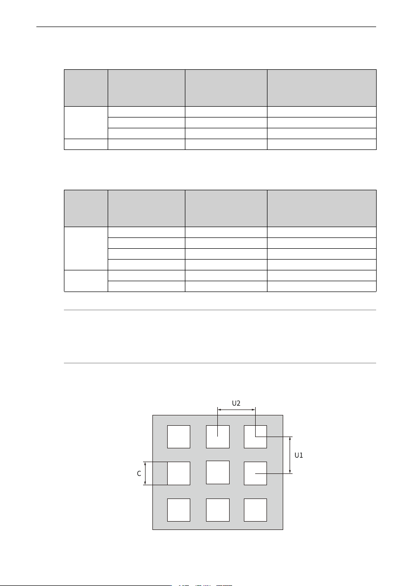
For example, on the plate shown in the following figure, the size of each hole is C x C,
and there are 9 holes. Therefore, the ventilation area of the air outlet is 9 x C x C.