MD600 Series Compact AC Drive Hardware Guide-EN-B06.PDF - 第55页
Electrical Design ‑ 54 ‑ No. Step 7 Install a magnetic ring to the U, V, and W output cables at the drive side and wind the cables through the magnetic ring for two to four turns. 8 Use shielded power cables with the shi…
Electrical Design
‑53‑
No. Step
7
Install a magnetic ring to the U, V, and W output cables at the
drive side and wind the cables through the magnetic ring for two
to four turns.
8
Use shielded power cables with the shield grounded properly.
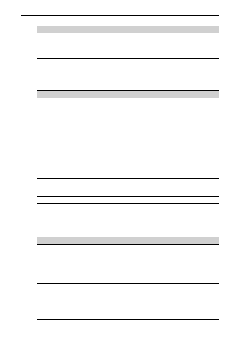
4.6.3.2 Common I/O Signal Interference
Refer to the following table to rectify the fault.
No. Step
1
Use shielded cables as the I/O signal cables and connect both
ends of the shield to the PE terminal.
2
Connect the PE terminal of the motor to that of the drive, and
connect the PE terminal of the drive to that of the power grid.
3
Add an equipotential bonding grounding cable between the host
controller and the drive.
4
Install a magnetic ring to the U, V, and W output cables at the
drive side and wind the cables through the magnetic ring for two
to four turns.
5
Increase the capacitor filtering of the low-speed DI, with a
recommended maximum value of 0.1 μF.
6
Increase the filtering capacitance of the AI. The recommended
maximum value is 0.22 uF.
7
Install a ferrite clamp or a magnetic ring to the signal cable and
wind the signal cable through the magnetic ring for one to two
turns.
8
Use shielded power cables with the shield grounded properly.
4.6.4 RS485 and CAN Communication Interference
Obverse the following steps for troubleshooting.
No. Step
1
Install a 120 Ω termination resistor at both ends of the bus.
2
Replace with multi-conductor shielded twisted pair cables and
ground both ends of the shield.
3
Separate communication cables from power cables with a
distance of at least 20 cm.
4
Adopt the daisy chain mode for multi-node communication.
5
Install extra equipotential bonding grounding cables among the
nodes in case of multi-node communication.
6
Add a ferrite clamp at both ends of the communication cable or
add a magnetic ring at both ends of the communication cable and
wind the communication cable through the magnetic ring for one
to two turns.

Electrical Design
‑54‑
No. Step
7
Install a magnetic ring to the U, V, and W output cables at the
drive side and wind the cables through the magnetic ring for two
to four turns.
8
Use shielded power cables with the shield grounded properly.
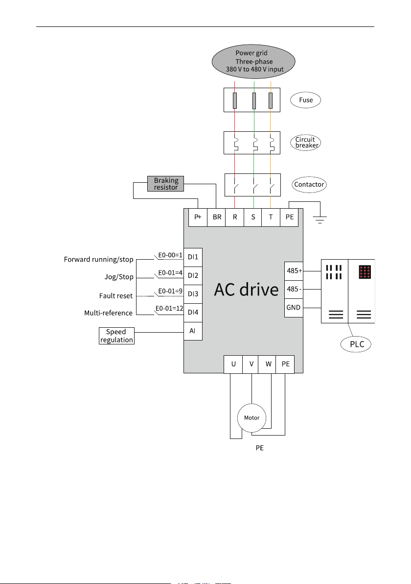
This section takes feeding of punch press as an example to describe a typical application
of electrical design of the AC drive.
Basic information
Basic information of the AC drive
● : Voltage of three-phase 380 V to 480 V; power of 2.2 kW; braking resistor required
● Application: Inovance PLC+HMI; RS485 communication
● I/O requirements: Four DIs to control start/stop and forward/reverse running; reset
upon fault; speed adjustment by external potentiometer connecting to AI
Electrical cabinet schematic diagram
The following figure shows the schematic diagram of the electrical cabinet based on the
background information of the project.