MD600 Series Compact AC Drive Hardware Guide-EN-B06.PDF - 第116页
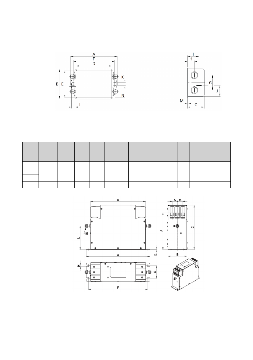
Option ‑115‑ Dimensions ● Dimensions of Schaffner FN2090 filters: Figure 12‑12 Dimensions of FN2090 filters (unit: mm) Table 12–14 Dimensions of FN2090 filters (unit: mm) Rated current (A) A B C D E F G H I J K L M N 3 8…
Option
‑114‑
Model selection
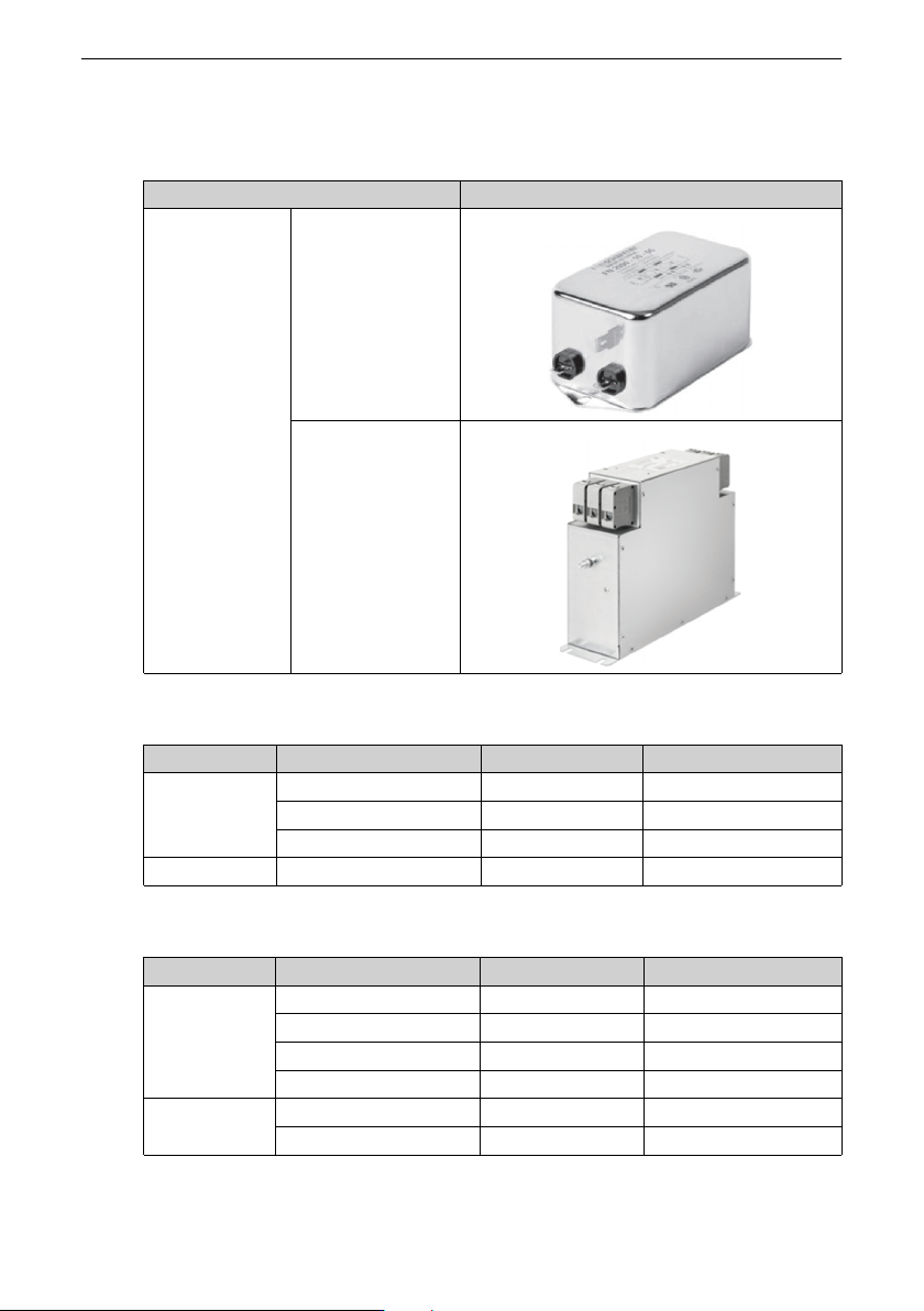
Table 12–11 Standard EMC filter model and appearance
Filter model
Appearance
Schaffner
FN2090
FN3287
Table 12–12 Selection of EMC filters (single-phase 200-240 V)
Structure
Model Rated Current (A) Applicable filter
T1
MD600S/A-2S2R8(B)
6.2 FN2090-8-06
MD600S/A-2S4R6(B)
10.2 FN 2090-12-06
MD600S/A-2S7R5(B)
16.6 FN 2090-20-06
T2
MD600S/A-2S010(B)
22.2 FN 2090-30-08
Table 12–13 Selection of EMC filters (three-phase 380-480 V)
Structure
Model Rated Current (A) Applicable filter
T1
MD600S/A-4T1R6(B)
1.9 FN3287-10-44-C28-R65
MD600S/A-4T2R3(B)
2.8 FN3287-10-44-C28-R65
MD600S/A-4T4R8(B)
5.9 FN3287-10-44-C28-R65
MD600S/A-4T5R5(B)
6.7 FN3287-10-44-C28-R65
T2
MD600S/A-4T9R5(B)
11.6 FN3287-16-44-C33-R65
MD600S/A-4T013(B)
15.8 FN3287-16-44-C33-R65
Option
‑115‑
Dimensions
● Dimensions of Schaffner FN2090 filters:
Figure 12‑12 Dimensions of FN2090 filters (unit: mm)
Table 12–14 Dimensions of FN2090 filters (unit: mm)
Rated
current
(A)
A B C D E F G H I
J
K L M N
3
85 54 30.3 64.8 49.8 75 27 12.3 20.8 19.9 5.3 6.3 0.7 6.3 × 0.84
6
8 113.5±1 57.5±1 45.4±1 94±1 56 103 25 12.4 32.4 15.5 4.4 6 1 6.3 × 0.8
● Dimensions of Schaffner FN3287 filters:
Figure 12‑13 Dimensions of FN3287 filters (unit: mm)

Option
‑116‑
Table 12–15 Dimensions of FN3287 filters (unit: mm)
Rated
current
(A)
A B C D E F G H
J±2
K L±1 M
10 180 40 112 153 0.8 170 20 4.5 94 11 68 M5
16 200 45 112 170 0.8 185 25 5.4 102 11 76 M5
25 205 45 132 173 0.8 190 25 5.4 113 13 83 M5
Note
If you need an EMC filter of Schaffner, you can purchase it from the manufacturer.
12.7 Braking Resistor
Braking resistor protection
In applications where a braking resistor is installed, it is recommended to use a resistor
with a temperature switch to ensure safety and avoid overheating and burning of the
braking resistor. Connect the temperature switch output to the electromagnetic contactor
control circuit on the front end of the drive (as shown in the following figure) to
implement the interlock protection function. When the resistor overheats, a tripping fault
occurs, avoiding the resistor to be burned.