MD600 Series Compact AC Drive Hardware Guide-EN-B06.PDF - 第38页
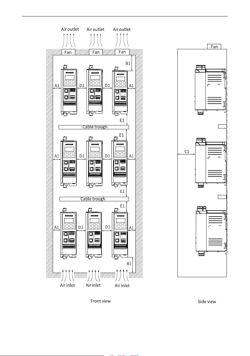
Electrical Design ‑37‑ Figure 4‑7 Clearance for device installation at different layers

Electrical Design
‑36‑
Note
● Three-phase 0.37 kW to 0.75 kW models and single-phase 0.37 kW models are
naturally ventilated, whereas the rest models are air-cooled.
● For the naturally-ventilated models, if they are installed side-by-side, a distance
of at least 30 mm must be reserved between two adjacent models.
● The air-cooled model supports side-by-side mounting without any space
between two models.
● When devices are installed at different layers, the minimum distance between two
layers is shown below.
Electrical Design
‑38‑
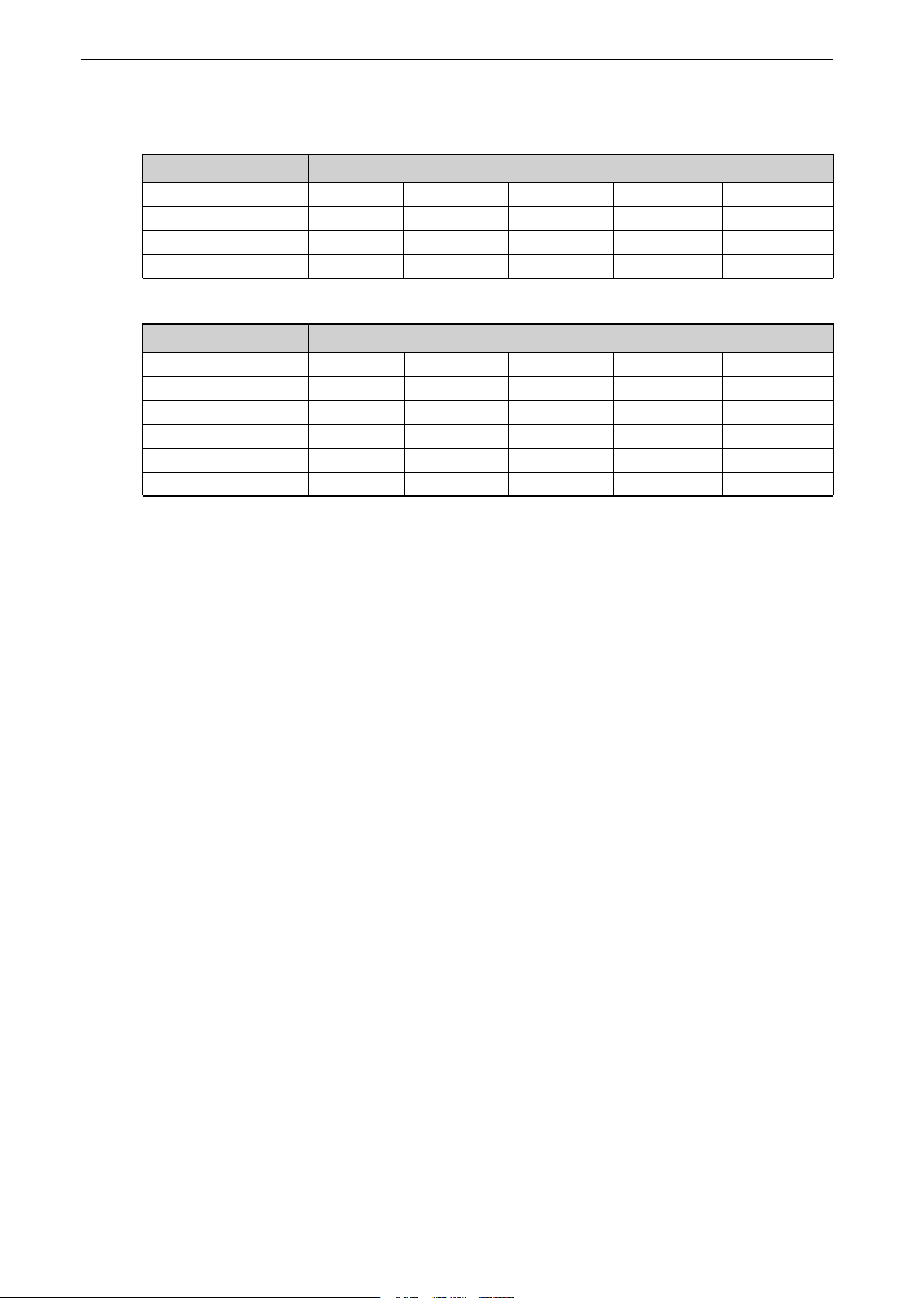
Table 4–6 Clearance for device installation at different layers (single-phase 200 V to 240
V)
Power Rating (kW) Clearance (mm)
0.37 A1 ≥ 20 B1 ≥ 100 C1 ≥ 80 D1 ≥ 30 E1 ≥ 80
0.75 A1 ≥ 20 B1 ≥ 100 C1 ≥ 80 D1 ≥ 0 E1 ≥ 80
1.5 A1 ≥ 20 B1 ≥ 100 C1 ≥ 80 D1 ≥ 0 E1 ≥ 80
2.2 A1 ≥ 20 B1 ≥ 120 C1 ≥ 80 D1 ≥ 0 E1 ≥ 80
Table 4–7 Clearance for device installation at different layers (three-phase 380 V to 480 V)
Power Rating (kW) Clearance (mm)
0.37 A1 ≥ 20 B1 ≥ 100 C1 ≥ 80 D1 ≥ 30 E1 ≥ 80
0.75 A1 ≥ 20 B1 ≥ 100 C1 ≥ 80 D1 ≥ 30 E1 ≥ 80
1.5 A1 ≥ 20 B1 ≥ 100 C1 ≥ 80 D1 ≥ 0 E1 ≥ 80
2.2 A1 ≥ 20 B1 ≥ 100 C1 ≥ 80 D1 ≥ 0 E1 ≥ 80
4 A1 ≥ 20 B1 ≥ 120 C1 ≥ 80 D1 ≥ 0 E1 ≥ 80
5.5 A1 ≥ 20 B1 ≥ 120 C1 ≥ 80 D1 ≥ 0 E1 ≥ 80
4.5.2 Heat Dissipation Design
4.5.2.1 Ventilation Requirements
Common heat dissipation methods include the following:
● Natural ventilation
● Forced air cooling
4.5.2.1.1 Air Duct Design
Heat dissipation design of the cabinet door
The cabinet is forcibly cooled by a built-in fan. Therefore, to ensure that enough cooling
air enters the cabinet, open an air inlet with an appropriate size on the cabinet door. For
details on the effective area of the air inlet, see
"4.5.2.1.2 Air Outlet and Inlet
"
on page 39
.
The air flows from bottom to top after being heated. Therefore, the cabinet air inlet must
be at least 50 mm lower than the air inlet of the drive, as shown below.