MD600 Series Compact AC Drive Hardware Guide-EN-B06.PDF - 第121页
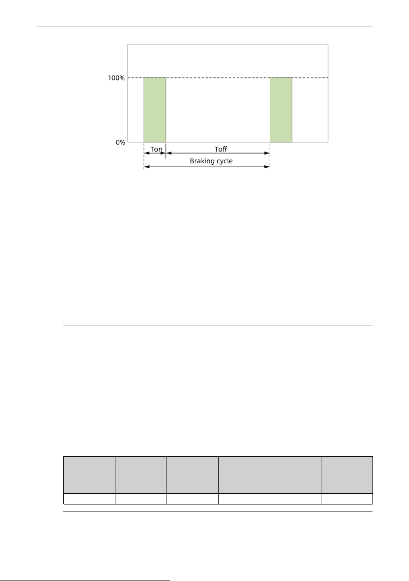
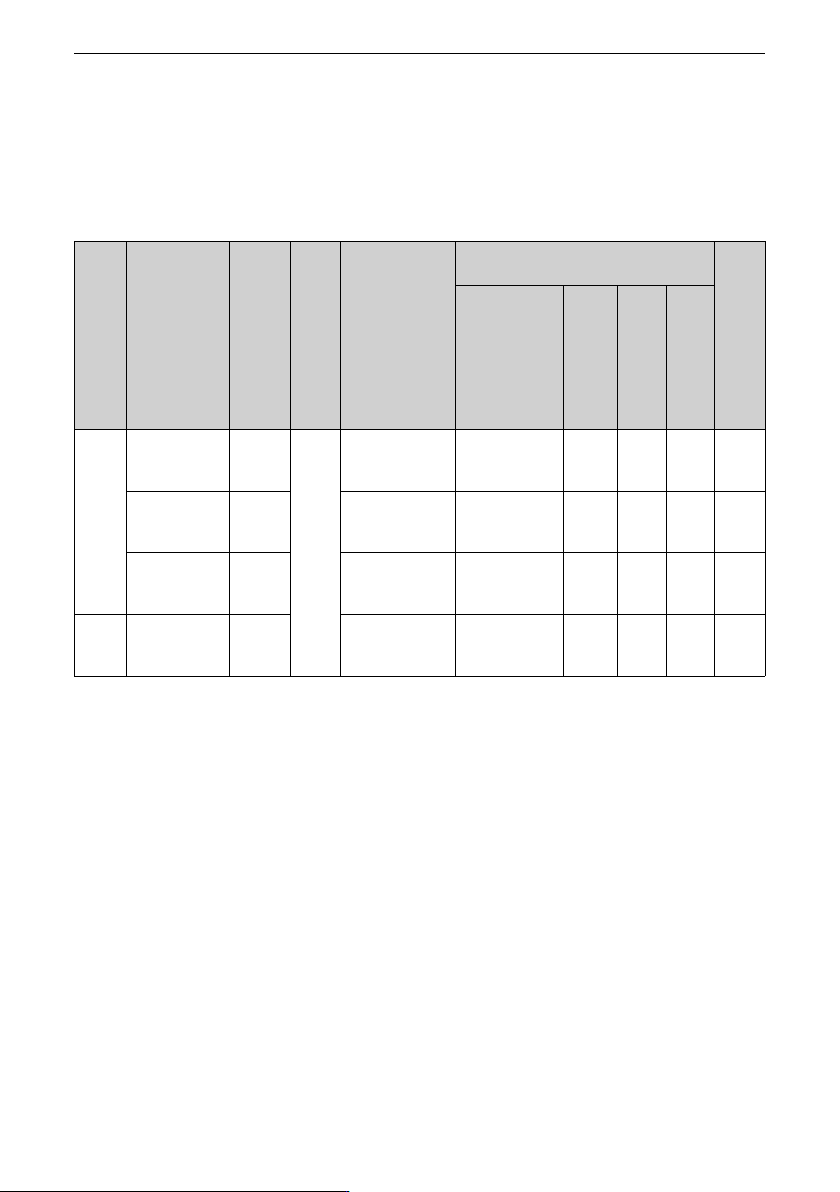
Option ‑ 120 ‑ Recommendation for typical braking resistor Assuming the braking torque of 125%, braking resistor ON time (T on ) of 10s per braking cycle, and braking duty cycle (ED%) of 10%, the resistance and power rat…
Option
‑119‑
P
N_BR
: Rated power of the braking resistor
α: Power derating value of the braking resistor, which is 50% generally. Depending on
the motor type and the actual cooling conditions of the resistor, a higher derating value
is required if the temperature of the resistor rises. Otherwise, a fire caused by
overheating of the resistor may occur. Select the power according to the actual
application conditions.
ED%: Braking duty cycle
T
on
: Indicates the time during which the braking resistor is turned on within one braking
cycle.
T
off
: Indicates the time during which the braking resistor is turned off within one braking
cycle.
Note
1. Braking resistor temperature rise: It is affected by various factors, such as the braking
on time T
on
, braking duty cycle ED%, actual heat dissipation conditions, and braking
resistor type (such as aluminum‑housed resistors, corrugated resistors, and braking
resistor cabinets with different designed thermal time constants). If the resistor
temperature rise is excessive, a higher power derating is required; otherwise, the risk
of fire can be incurred due to overtemperature of the braking resistor. Therefore, select
the braking resistor with a proper power class according to actual conditions.
2. Braking duty cycle (ED%): It must be determined based on the actual braking
conditions. Typical ED% values for common applications are listed in the following
table.
Common
applica-
tions
Elevator Winding/
Unwinding
Centrifuge Occasional
braking
load
General
application
ED% 20% to 30% 20% to 30% 50% to 60% 5.0% 10%
Option
‑120‑
Recommendation for typical braking resistor
Assuming the braking torque of 125%, braking resistor ON time (T
on
) of 10s per braking
cycle, and braking duty cycle (ED%) of 10%, the resistance and power ratings of the
braking resistor are shown in the table below.
Table 12–16 Selection of braking resistors (single-phase 200-240 V)
Struc
ture
Model
Applica
ble
motor
(kW)
Brak
ing
unit
Specifications of
the
recommended
braking resistor
(125% braking
torque, 10% ED,
max. 10s)
Actual braking resistor selection (Inovance
model)
Mini
mum
baking
resist
ance
(Ω)
Braking resistor
model
Resist
ance of
a
single
resistor
(Ω)
Power
of a
single
motor
(W)
Num
ber of
paral
lel
resis
tors
(PCS)
T1
MD600S/A-
2S2R8(B)
0.37
Built-
in unit
(op
tional)
60 W/370 Ω
RXLG-200W-
380RJ-XZ1000-
OE-B
380 200 1 52
MD600S/A-
2S4R6(B)
0.75 110 W/180 Ω
RXLG-400W-
190RJ-XZ1000-
OE-B
190 400 1 52
MD600S/A-
2S7R5(B)
1.5 230 W/90 Ω
RXLG-800W-
100RJ-XZ1000-
OE-B
100 800 1 35
T2
MD600S/A-
2S010(B)
2.2
330 W/60 Ω
RXLG-1500W-
62RJ-XZ1000-
OT-B
62 1500 1 26
Option
‑121‑
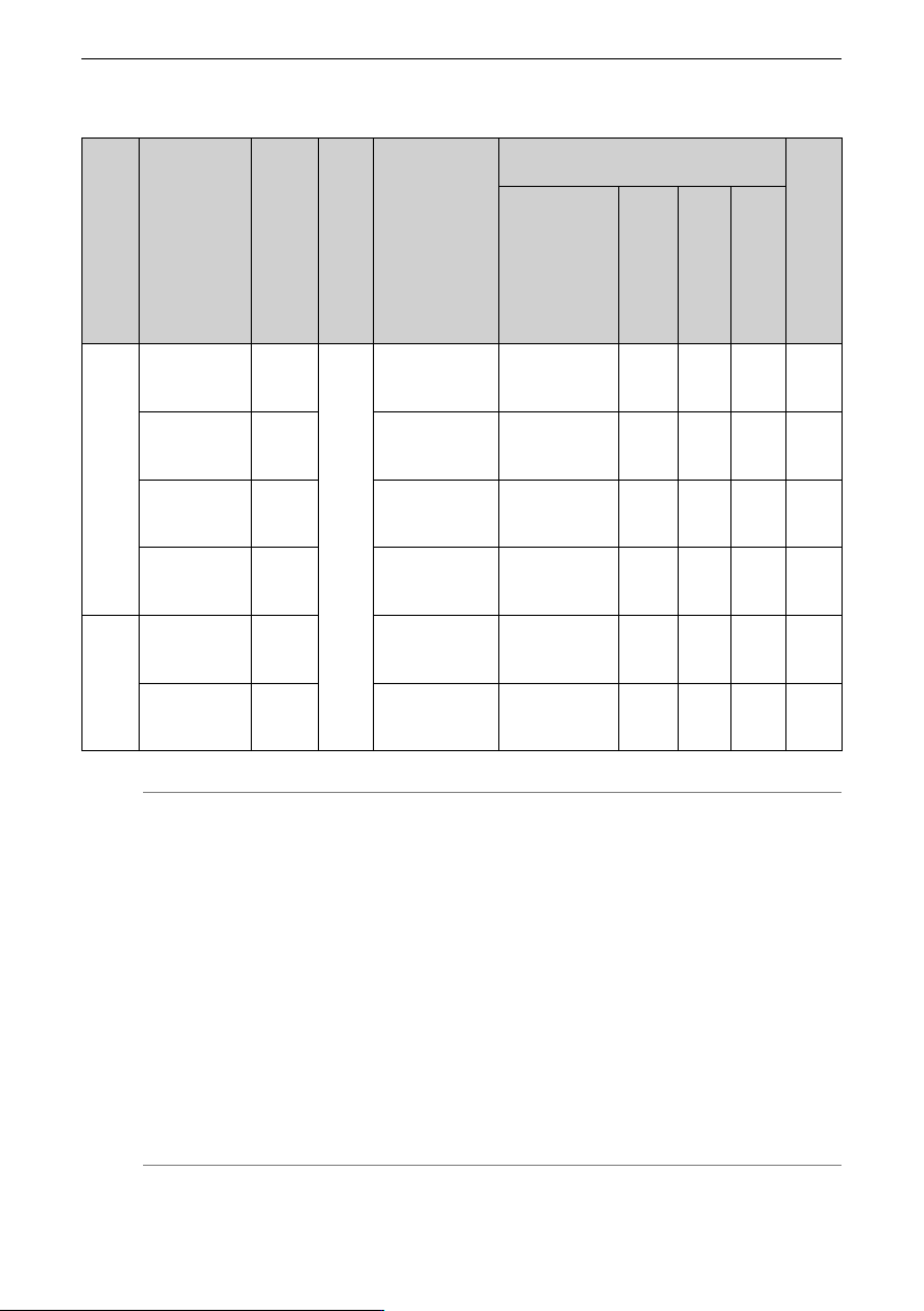
Table 12–17 Selection of braking resistors (three-phase 380 V to 480 V)
Struc
ture
Drive model
Applica
ble
motor
(kW)
Brak
ing
unit
Specifications of
the
recommended
braking resistor
(125% braking
torque, 10% ED,
max. 10s)
Actual braking resistor selection (Inovance
model)
Mini
mum
baking
resist
ance
(Ω)
Braking resistor
model
Resist
ance of
a
single
resistor
(Ω)
Power
of a
single
motor
(W)
Num
ber of
paral
lel
resis
tors
(PCS)
T1
MD600S/A-
4T1R6(B)
0.37
Built-
in unit
(op
tional)
60 W/1560 Ω
RXLG-50W-
1560RJ-XZ1000-
OE-B
1560 50 1 69
MD600S/A-
4T2R3(B)
0.75 110 W/770 Ω
RXLG-100W-
770RJ-XZ1000-
OE-B
770 100 1 69
MD600S/A-
4T4R8(B)
1.5 230 W/380 Ω
RXLG-200W-
380RJ-XZ1000-
OE-B
380 200 1 69
MD600S/A-
4T5R5(B)
2.2 330 W/260 Ω
RXLG-300W-
260RJ-XZ1000-
OE-B
260 300 1 69
T2
MD600S/A-
4T9R5(B)
4 600 W/140 Ω
RXLG-600W-
140RJ-XZ1000-
OE-B
140 600 1 41
MD600S/
A‑4T013(B)
5.5 830 W/100 Ω
RXLG-800W-
100RJ-XZ1000-
OE-B
100 800 1 41
Note
● The braking resistance in the above table is under the condition of 125% braking
torque, 10s braking on-time (Ton), and 10% braking duty cycle (ED%).
● For single-phase 200 V to 240 V, the default initial braking voltage of the built-in
braking unit is 370 V. For three-phase 380 V to 480 V, the default initial braking
voltage of the built-in braking unit is 760 V.
● The data in the preceding table is only for reference. You can select the
resistance and power of the braking resistor as required. (Note that the
resistance cannot be lower than the recommended minimum value, whereas the
power can exceed or be equal to the recommended value.) Select the braking
resistor based on the generation power of the motor in the actual system,
system inertia, deceleration time, and potential energy load.
● For systems featuring large inertia frequent braking and requiring short
deceleration time, select a braking resistor with high power and low resistance.