MD600 Series Compact AC Drive Hardware Guide-EN-B06.PDF - 第88页
Maintenance and Repair ‑87‑ Item Description Solution Checked Drive There are no waste, dirt, or dust on the surface. ● Ensure that the power supply of the controller cabinet is connected. ● Use a vacuum cleaner to suck …
Maintenance and Repair
‑86‑
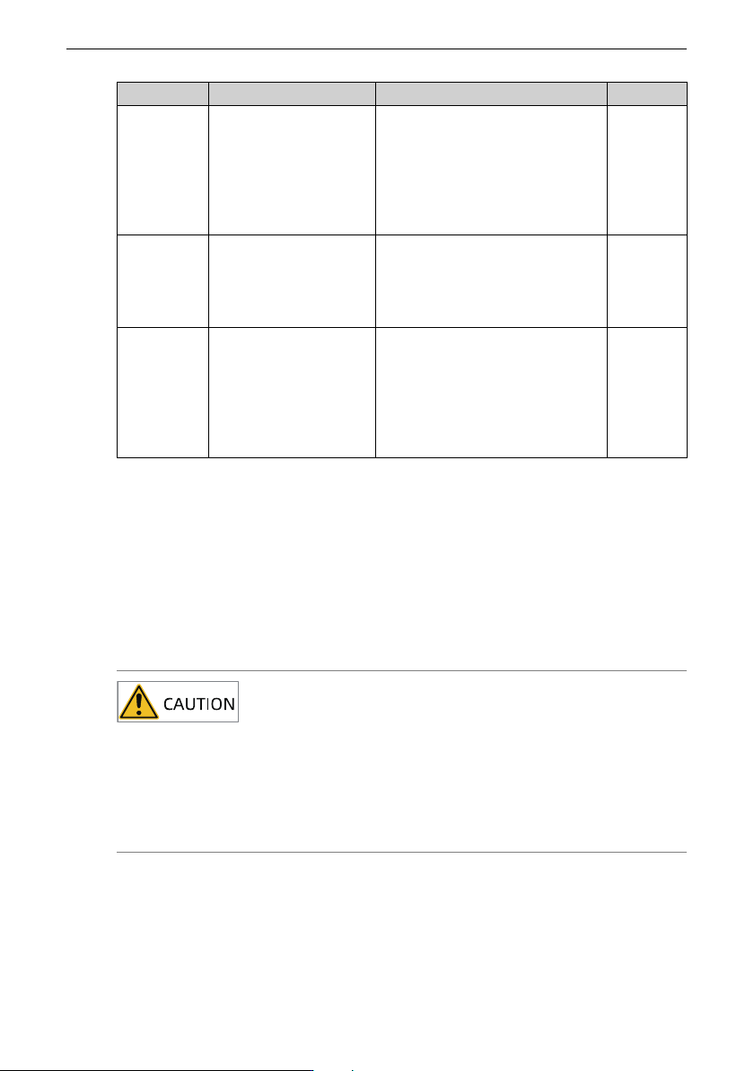
Item
Description Solution Result
Load The operating current of
the drive is within the
allowable range of the
rated current of the
drive and that of the
motor.
● Ensure motor parameters are set
properly.
● Ensure that the motor is not
overloaded.
● Ensure that the mechanical
vibration is within the allowable
range, that is, lower than 0.6 g.
Input
voltage
The power supply
voltage between the
main circuit and the
control circuit is normal
and stable.
● Ensure that the input voltage is
within the allowable range.
● Check that no heavy load is
started around the drive.
Brake The brake circuit is
normal.
● Check that the control wiring is
secure and free from
discoloration, melting, or other
abnormalities.
● Ensure that the brake acts
properly. Perform the brake
action test separately.
10.1.2Regular checklist
The following shows items to be checked every one or two years. Determine the actual
inspection cycle based on actual application and operating environment. Regular
maintenance helps detect product function deterioration and damage.
Make a copy of the following checklist and sign the "Checked" column after each
inspection.
Do not perform inspection or connection work with power on. Failure to do so may result
in an electric shock. Cut off the power supplies of all equipment before wiring or repair.
Wait for at least the time designated on the equipment warning label before further oper-
ations because residual voltage still exists after power-off. After waiting for the desig-
nated time, measure the DC voltage in the main circuit to ensure the DC voltage is within
the safety voltage range. Failure to do so may result in an electric shock.
Maintenance and Repair
‑87‑
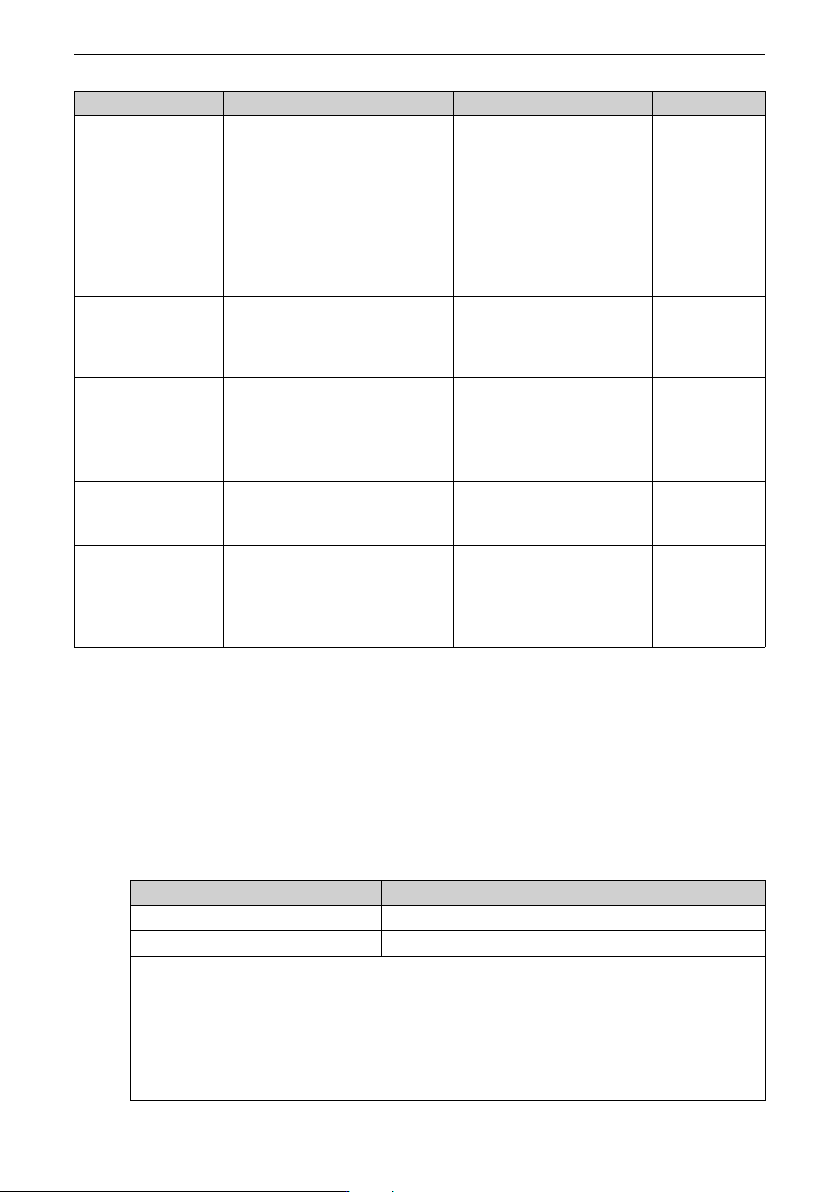
Item Description Solution Checked
Drive There are no waste, dirt, or dust on
the surface.
● Ensure that the power supply
of the controller cabinet is
connected.
● Use a vacuum cleaner to suck
up waste and dust to prevent
direct contact with the parts.
● For stubborn surface dirt, wipe
up the dirt with a piece of soft
cloth immersed in alcohol.
Cable
● Power cables and connections are
not discolored.
● The insulation is not aged or
cracked.
● Replace the cracked cables.
● Replace the damaged
terminal.
Peripherals of the
electromagnetic
contactor
● The contact can be closed without
abnormal noise.
● There are no short circuit, water
seepage, swelling, or cracking
occurs on peripheral devices.
Replace such defective
peripherals.
Air duct
● The air duct and heatsink are not
clogged.
● The fan is operating normally.
● Clean the air duct.
● Replace the fan.
Control circuit
● Control components are in good
contact.
● Terminal screws are tightened.
● The insulation of the control cable is
not cracked.
● Clean the surface of control
circuit cables and terminals.
● Replace control circuit cables
that are damaged or corroded.
10.2 Components Replacement
10.2.1Service Life of Maintainable Components
The quick-wear parts of the AC drive include the cooling fan and filter electrolytic
capacitor. The service life of such devices is closely related to the operating environment
and maintenance conditions. Generally, the lifespan is as follows.
Part
Service Life
[Note]
Fan
≥ Five years
Electrolytic capacitor
≥ Five years
Note:
The standard lifetime indicates the lifetime when the parts are used in the following
conditions. You can determine when to replace these parts according to the actual
operating time.
Ambient temperature: 40°C
Load rate: 80%
Operating rate: 24 hours per day
Maintenance and Repair
‑88‑
10.2.2Replacing the Fan
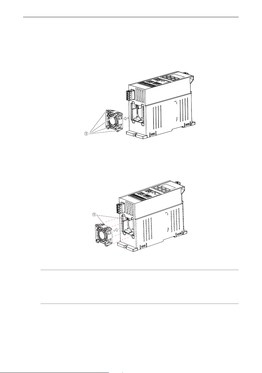
Removing the fan
The MD600 fan can be removed without any tool.
Press and hold the four snap-fit joints around the fan to pull the fan out, as shown by ①.
Figure 10‑1 Fan removal
Installing the fan
Align the fan terminal with the slot as shown in ① and push the fan toward the drive until
the snap-fit joints are in the places.
Figure 10‑2 Fan installation
Note
For RS485 and CAN models, single-phase 0.75 kW, 1.5 kW, and 2.2 kW AC drives, as well
as three-phase 1.5 kW, 2.2 kW, 4 kW, and 5.5 kW AC drives provide one fan.