MD600 Series Compact AC Drive Hardware Guide-EN-B06.PDF - 第45页
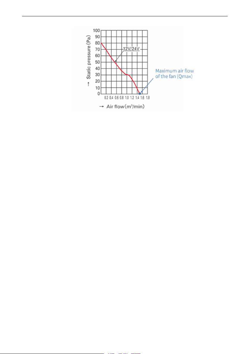
Electrical Design ‑ 44 ‑ Note ● The air volume of the selected fan cannot be smaller than the maximum air volume Qmax. If a single fan cannot meet this requirement, multiple fans can be used. ● Install the fan in the cor…
Electrical Design
‑43‑
The preceding tables apply to only an individual product. When multiple products are
installed in the cabinet, calculate the total air volume by adding the air volume of each
product.
For example, a cabinet contains the following units: T1 model (single-phase 0.37 kW) +
T1 model (single-phase 1.5 kW) + T2 model (single-phase 2.2 kW) + T1 model (three-
phase 0.75 kW) + T1 model (three-phase 2.2 kW) + T2 model (three-phase 4 kW).
Therefore, the minimum ventilation value of the cabinet fan should be 0 + 22 + 38 + 0 + 22
+ 38 = 120 CFM.
4.5.2.2 Fan Design
The MD600 fan is designed with a separate fan duct and supports forward and reverse
rotation of the fan.
To select the fan, do the following:
1. Calculate the sum of cooling air volume required by all the devices based on "
Table 4–
13
"
on page 42
and "
Table 4–12
"
on page 42
.
2. Determine the maximum air volume value (Qmax).
3. Determine the specification and quantity of the fan based on the maximum air volume
(Qmax).
Where:
Qmax = (1.3 to 1.5) × Sum of cooling air volume
Qmax = (1.6 to 2.2) × Sum of cooling air volume (if a mesh filter or other components
are installed at the cabinet air outlet)
Electrical Design
‑44‑
Note
● The air volume of the selected fan cannot be smaller than the maximum air
volume Qmax. If a single fan cannot meet this requirement, multiple fans can be
used.
● Install the fan in the correct air exhaust direction to ensure that air flows from
inside to outside of the cabinet. Otherwise, hot air cannot be exhausted and the
drive may be overheated or damaged.
4.5.3 EMC-Compliant Cabinet Design
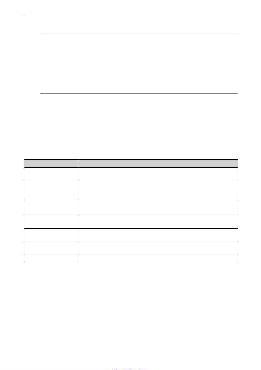
To prevent electromagnetic interference in the cabinet, isolate interference sources from
devices that may be interfered during installation. Divide a cabinet into multiple EMC
compartments or use multiple cabinets based on the intensity of interference sources,
and install each device in accordance with the following wiring principles.
Table 4–14 Wiring Principle
No.
Wiring Principle
1
Install the control devices and the drive devices in two different
cabinets.
2
If multiple cabinets are used, use grounding cables with a cross-
sectional area of at least 16 mm2 to connect different cabinets,
therefore realizing equipotential bonding between the cabinets.
3
Place the devices in different areas in the cabinet according to the
device signal strength.
4
Carry out equipotential bonding for the devices in different areas of
the cabinet.
5
Shield all communication (such as RS-485) signal cables leading from
the cabinet.
6
Install the power supply input filter close to the cabinet input
interface.
7
Spray each grounding point in the cabinet.
Electrical Design
‑45‑
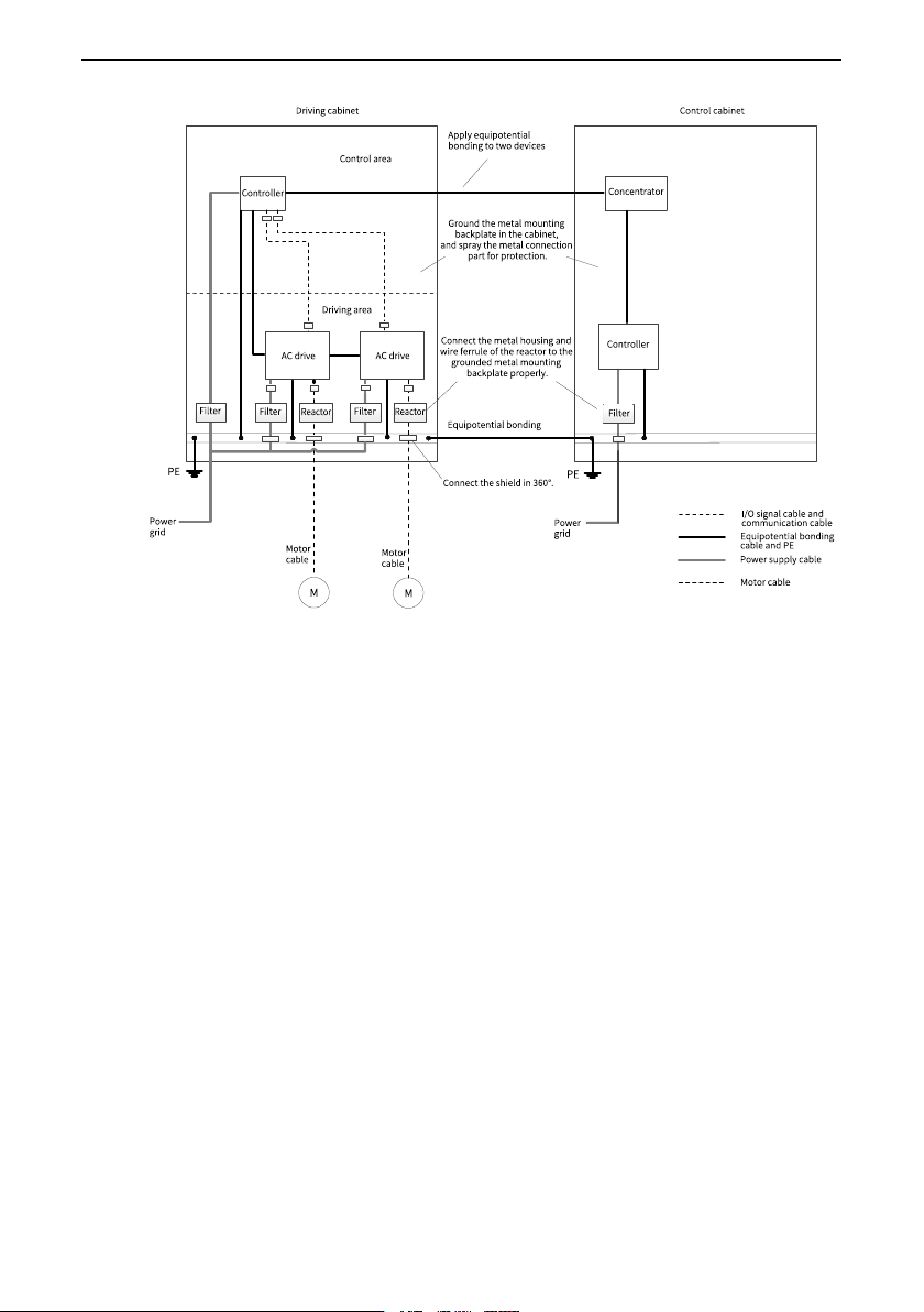
Figure 4‑9 Recommended wiring of the cabinet system
Routing Precautions
● Main circuit cabling requirements
The power supply input cable of the AC drive and motor cable can generate strong
electromagnetic interference. To avoid electromagnetic interference caused by long-
distance parallel coupling between the strong disturbing cable and control circuit,
ensure a distance longer than 20 cm between main circuit cables and signal cables
when cabling. Main circuit cables include the input R/S/T cable, output U/V/W cable,
DC bus, and braking cable. Signal cables include the I/O signal cable and
communication cable.
Cable ducts must be in good connection and well grounded. Aluminum cable ducts
can be used to ensure equipotentiality of the device. Connect the AC drive and motor
to the system (machines or devices) properly. Protect all connections with spray
coating and ensure good contact of conductive metal.