MD600 Series Compact AC Drive Hardware Guide-EN-B06.PDF - 第125页
Option ‑ 124 ‑ Table 12–18 Appearance and model of the magnetic ring and ferrite clamp Category Manufacturer model Appearance Magnetic ring DY644020H DY805020H DY1207030H Ferrite clamp DYR-130-B Dimensions Figure 12‑14 D…

Option
‑123‑
Note
1. The thermal time constant τ of the braking resistor must be larger than or equal to
100s.
2. The recommended power of the braking resistor in the preceding table is based on the
assumption that the braking torque is 125%. If Ton and ED% remain unchanged but the
braking torque changes, the power of the braking resistor changes linearly with the
braking torque. For example, the recommended power of the braking resistor for a 5.5
kW AC drive under the condition of "braking torque 125%, ED 10%, and 10s" is 830 W. If
the actual braking torque is 150% (1.2 times the braking torque 125%), the
recommended power of the braking resistor under the condition of "braking torque
150%, ED 10%, 10s" is 996 W (830 W x 1.2).
3. The temperature rise of the braking resistor varies with different heat dissipation
conditions. Therefore, the heat dissipation conditions of the resistor can also affect the
power selection of the braking resistor.
12.8 Ferrite Ring and Ferrite Clamp
Model selection
The magnetic ring can be used on the input or output side of the AC drive. Install it as
close to the AC drive as possible. When installed on the input side, the ferrite ring can be
used to suppress the noise in the input power supply system of the drive. When installed
on the output side, the magnetic ring can suppress interference generated by the AC
drive to external devices and reduce the bearing current.
In applications with leakage current and signal cable interference, install a magnetic ring
or a ferrite clamp.
● The amorphous magnetic ring has a high magnetic conductivity when the frequency
is within 1 MHz and can efficiently suppress interference of the servo drive at a high
cost.
● Ferrite clamp: featuring high permeability when the frequency is above 1 MHz and
excellent suppression performance on interference generated by low-power drives
and signal cables
DY644020H, DY805020H, and DY1207030H are all amorphous magnetic rings.
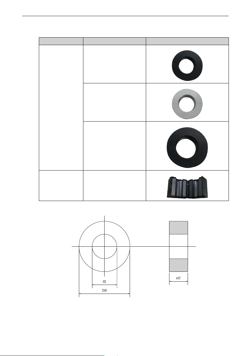
Option
‑125‑
Table 12–19 Dimensions of the magnetic ring
Model
Dimensions (OD × ID × HT) (mm)
DY644020H 64 × 40 × 20
DY805020H 80 × 50 × 20
DY1207030H 120 × 70 × 30
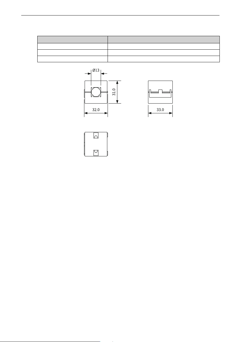
Figure 12‑15 Dimensions of the ferrite clamp (unit: mm)
12.9 Cable
12.9.1Main circuit cable
Power cable selection requirements
For selection of power cables, follow national or regional regulations. Select IEC cables
according to the following requirements:
● Compliant with EN 60204-1 and IEC 60364-5-52 standards
● PVC insulated cables with copper conductors
● Heat resistance: maximum cable surface temperature not exceeding 70°C at an
ambient temperature of 40°C (Note: Contact the manufacturer when the ambient
temperature exceeds 40°C.)
● Symmetric cable with copper-braided shield
If the recommended cables for peripheral equipment or options are not suitable for the
product, contact Inovance.
To comply with the EMC standards, use shielded cables. Shielded cables are classified
into the three-conductor cables and four-conductor cables, as shown in the following
figure. If a three-conductor cable is used but its shield cannot provide sufficient
conductivity, add an independent PE cable. Alternatively, use a four-conductor cable