00196962-04-BA-SX12-V2-EN.pdf - 第113页
User manual SIPLACE SX1/SX2 3 Technical data and assemblies From software version SC 706.1 SP1 Version 10/2014 3.5 Placement head 113 3 Fig. 3.5 - 5 SIPLACE MultiSt ar - back vie w , function groups part 3 (1) Comp onent…
3 Technical data and assemblies User manual SIPLACE SX1/SX2
3.5 Placement head From software version SC 706.1 SP1 Version 10/2014
112
3
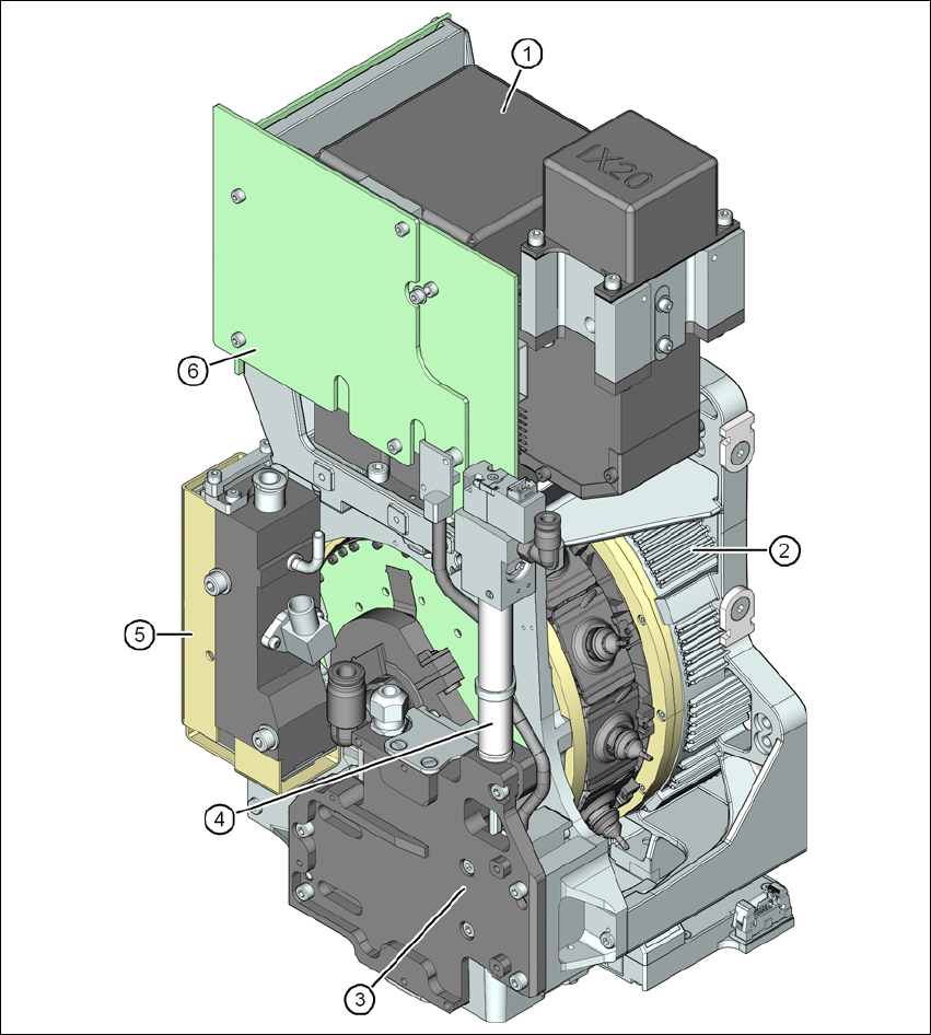
Fig. 3.5 - 4 SIPLACE MultiStar - front view, function groups part 2
(1) C&P component camera, type 30, 27 x 27, digital
(2) Torque motor for star drive
(3) Z drive (linear motor)
(4) Return cylinder
(5) Pressure control valve
User manual SIPLACE SX1/SX2 3 Technical data and assemblies
From software version SC 706.1 SP1 Version 10/2014 3.5 Placement head
113
3
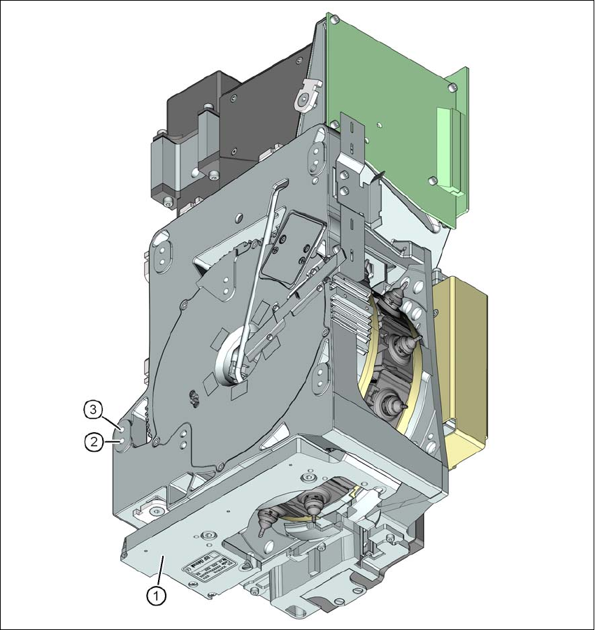
Fig. 3.5 - 5 SIPLACE MultiStar - back view, function groups part 3
(1) Component sensor
(2) Assembly position for component height of up to 11.5 mm
(3) Assembly position for component height of up to 6 mm
3 Technical data and assemblies User manual SIPLACE SX1/SX2
3.5 Placement head From software version SC 706.1 SP1 Version 10/2014
114
3.5.4.1 Description
The MultiStar combines the two opposing characteristics of high placement performance and high
flexibility. When handling smaller components, up to 27 mm x 27 mm, the MultiStar uses the Col-
lect&Place method to ensure higher placement performance. In this case, the components are op-
tically centered with the integrated component camera. When handling larger components, up to
50 mm x 40 mm, the placement head uses the Pick&Place principle, in which the components are
optically centered with the stationary camera.
The combination of the two placement principles C&P and P&P gave the MultiStar its name. It is
also known as the CPP head.
The 12 segments of the CPP head are arranged in the shape of a star. A torque motor with high
torque rotates the star around the horizontal axis, the star axis.
Each segment has its own DP drive for rotating the nozzle. The nozzles are therefore no longer
rotated into the correct position at a single head station. They can be rotated into their placement
position at any time and independently of one another.
Each segment has a separate vacuum generator. This greatly reduces the time taken to switch
between vacuum and air blast. It also allows a vacuum check to be carried out in the holding circuit
for each individual nozzle.
The Z drive for the segments is implemented with a linear motor with linear path measuring sys-
tem, and is thus extremely precise. In the pick-up/placement position, the Z drive moves the seg-
ments up or down in the vertical direction.
As in the case of all other SIPLACE Collect&Place heads, the digital component camera is inte-
grated into the placement head. The abolition of additional travel paths for optical centering of the
components leads to a higher processing speed.
The component sensor on the underside of the placement head measures the components at
the pickup/placement position. Measurements can be performed at the nozzle tip for each move-
ment of the Z axis and an ascertainment made as to whether there is a component on the nozzle
and how high the component is.
3.5.4.2 Assembly positions of SIPLACE MultiStar
The CPP head can be fitted to the head mount in two different positions:
– MultiStar in the top assembly position
In this position, all components can be processed up to a size of 50 mm x 40 mm and a height
of 11.5 mm. 3
– MultiStar in the bottom assembly position
In this position, the CPP head places components up to a size of
27 mm x 27 mm and a component height of 6 mm, using the Collect&Place method. 3