00196962-04-BA-SX12-V2-EN.pdf - 第130页
3 Technical data and assemblies User manual SIPLACE SX1/SX2 3.7 PCB conveyor system From software version SC 706.1 SP1 Version 10/2014 130 3.7.2 Design of the PCB single conveyor 3 Fig. 3.7 - 1 Design of the PCB single c…

User manual SIPLACE SX1/SX2 3 Technical data and assemblies
From software version SC 706.1 SP1 Version 10/2014 3.7 PCB conveyor system
129
3.7 PCB conveyor system
3.7.1 Description
The PCB conveyors are designed as three-part conveyors with input, processing and output con-
veyor sections. The input and output conveyor areas act as bumper zones for the boards in the
event of short waiting periods.
The conveyor belts are driven by brushless DC motors. Light barriers monitor and control trans-
portation of the boards. Once the board has reached the placement area and has passed the light
barriers, it is braked. As soon as the circuit board has reached its target position, a laser light bar-
rier is triggered, the conveyor belt is stopped and the board is clamped from below.
The distance between the top of the PCB and the placement head thus remains unchanged for
each PCB, and is not dependent on the thickness of the PCB. The placement rate is thus inde-
pendent of the PCB thickness. The PCB fiducial centering can also be optimized. Since the dis-
tance between the PCB surface and the PCB camera remains the same, the PCB camera is
always focussed on the PCB surface with the same sharpness. The PCB fiducial contours are op-
timally mapped on the CCD chip of the PCB camera.
The width of the circuit board conveyor is set and monitored by an integral control circuit. It can
be selected by calling up the program. The control electronics activate the drive motor until the
required width has been reached.
The conveyor height can be selected on the machine to allow the machines to be integrated into
lines with a conveyor height of, 900, 930 or 950 mm. The standard height is 930 mm.
The PCB conveyors communicate with the individual machines via the SMEMA interface or the
optional Siemens interface.
The fixed conveyor side can be either right or left in dual conveyors. Changing the fixed conveyor
side from left to right or vice versa is easily performed in the station software.
In single conveyors, only the fixed conveyor side can be set to the right-hand side. However, the
fixed conveyor side can be set to the left with mechanical conversion.
The Smart Pin Support option is used to position the support pins automatically under the board
on the lifting table. See also section 6.15
, page 346.
3 Technical data and assemblies User manual SIPLACE SX1/SX2
3.7 PCB conveyor system From software version SC 706.1 SP1 Version 10/2014
130
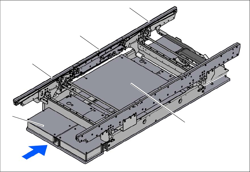
3.7.2 Design of the PCB single conveyor
3
Fig. 3.7 - 1 Design of the PCB single conveyor
(1) Input conveyor
(2) Processing conveyor
(3) Output conveyor
(4) Lifting table
(5) Conveyor control (under the cover)
(1)
(4)
(3)
(2)
(5)
User manual SIPLACE SX1/SX2 3 Technical data and assemblies
From software version SC 706.1 SP1 Version 10/2014 3.7 PCB conveyor system
131
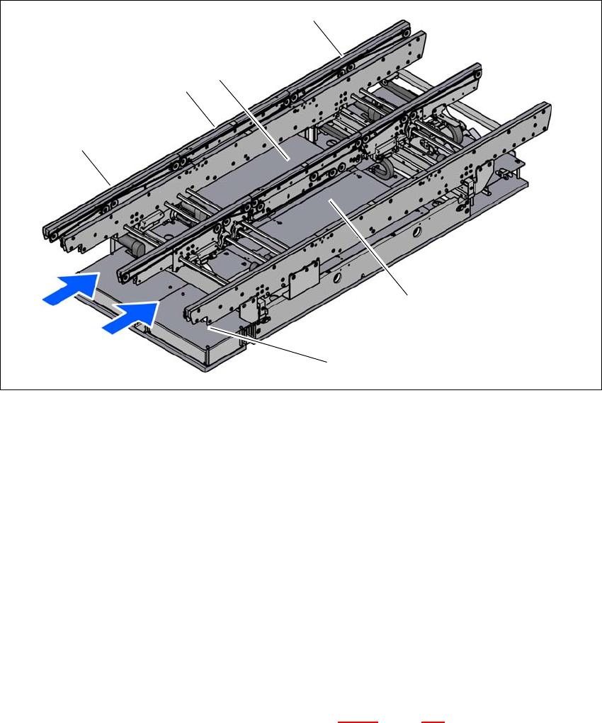
3.7.3 Structure of the flexible PCB dual conveyor
The flexible dual conveyor has two conveyor tracks that are electrically and mechanically inde-
pendent of one another. The fixed conveyor side is on the right as a standard. The PCB dual con-
veyor can be operated as a single or dual conveyor, according to your needs.
3
Fig. 3.7 - 2 Structure of the PCB dual conveyor
(1) Input conveyor
(2) Processing conveyor
(3) Lifting table 1
(4) Output conveyor
(5) Lifting table 2
(6) Conveyor control (under the cover)
T1 Conveyor track 1
T2 Conveyor track 2
3.7.3.1 Flexible PCB dual conveyor - lanes and types
The right-hand conveyor lane (viewed in the direction of transport) is known as "conveyor 1" while
the left conveyor lane is termed "conveyor 2" (see fig. 3.7 - 4
, page 133 ).
(5)
(1)
(4)
(T1)
(3)
(T2)
(2)
(6)