00196962-04-BA-SX12-V2-EN.pdf - 第212页
4 Setting up and commissioning Us er ma nual SIPLACE SX1/SX2 4.3 Setting up the machine From software version SC 706.1 SP1 Version 10/2014 212 4.3.8 Integrating the machine into the line Observe the g eneral wa rnings …
User manual SIPLACE SX1/SX2 4 Setting up and commissioning
From software version SC 706.1 SP1 Version 10/2014 4.3 Setting up the machine
211
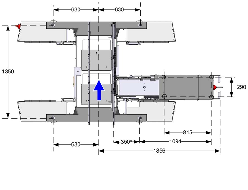
4.3.7.3 Machine foot clearances for the machine and WPC5/WPC6
4
Fig. 4.3 - 7 Machine foot clearances for the machine and WPC5/WPC6 in millimeters
a) The value depends on the position of the fixed side.
All dimensions in millimeters.

4 Setting up and commissioning User manual SIPLACE SX1/SX2
4.3 Setting up the machine From software version SC 706.1 SP1 Version 10/2014
212
4.3.8 Integrating the machine into the line
Observe the general warnings in section 4.3.1, page 200.
Observe the warnings for transportation of the machine in section 4.3.2, page 201.
For details of tools and equipment, refer to section 4.3.5, page 204.
4.3.8.1 Aligning and adjusting the machines in the line
With the fork-lift, raise the machine until the weight is taken off the machine feet.
Determine the PCB conveyor height for the machine in the line and use the hexagon socket
head screw to adjust the height approximately.
You may need to fit the machine feet to the relevant PCB conveyor height (see 4.3.6 on page
205).
Position the machine on the free location on the line using the fork-lift.
Pay attention to the alignment of the PCB conveyors and check the distance to the previous
machine.
4
4
Use the machine spirit level to align the machine in the X and Y directions (see 4.3.9 on page
213).
Align the PCB conveyors with the help of the long auxiliary board. Move the machine to its
final position. You must be able to push the long auxiliary board through the PCB conveyor to
the adjacent machine with ease and without jamming.
Use the machine spirit level to check the X and Y directions again and adjust the height of the
feet if necessary.
Tighten the machine feet at the clamping screw to a torque of 130 Nm.
Hit the feet with a hammer to check the load-bearing strength of the machine feet.
Use the machine spirit level to check the X and Y directions again.
WARNING
Risk of damage!
If the machine feet on one side hit the ground hard, the fixings may be damaged.
Lower the machine slowly.
A second person should look underneath to ensure that all the machine foot touch
the floor at the same time.
User manual SIPLACE SX1/SX2 4 Setting up and commissioning
From software version SC 706.1 SP1 Version 10/2014 4.3 Setting up the machine
213
4.3.9 Aligning the machine with the machine spirit level
4
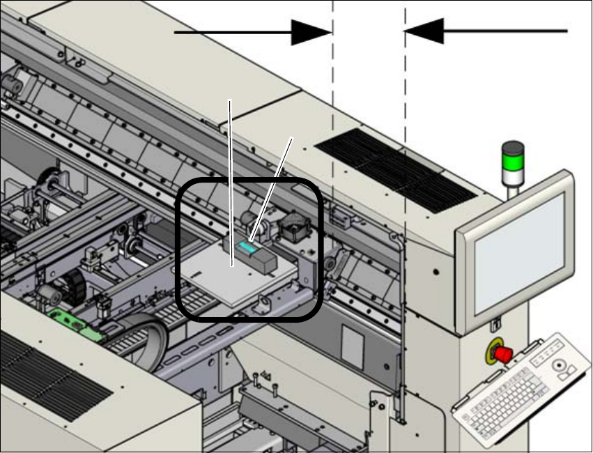
Fig. 4.3 - 8 Adjusting the machine in the X and Y directions - measurement procedure
Measurement is performed at gantry 1.
Push the gantry inwards, in the Y direction. The distance of the two bumpers should be ap-
prox. 300 mm (or approx. 4-5 red dots on the linear guide).
Place the support plate (1) onto the gantry so that the 3 support pins lie on the free areas be-
tween the running surface and the magnets. Make sure that the 3 support pins touch evenly.
Place the machine spirit level (measuring accuracy of 0.02 mm) onto the support plate and
measure at 3 points
– The alignment of the Y axis at the loose bearing side and at the fixed bearing side.
– The alignment of the X axis in the middle of the X gantry. The head mount must be in the
middle of the X gantry.
4
300 mm
(1)
(
2)