00196962-04-BA-SX12-V2-EN.pdf - 第146页
3 Technical data and assemblies User manual SIPLACE SX1/SX2 3.9 X feeder modules for SIPLACE SX1/SX2 From software version SC 706.1 SP1 Version 10/2014 146 3.9.1.5 Design of the t ape feeder module for the SIPLACE X-Seri…

User manual SIPLACE SX1/SX2 3 Technical data and assemblies
From software version SC 706.1 SP1 Version 10/2014 3.9 X feeder modules for SIPLACE SX1/SX2
145
3.9.1.4 Tape feeder module shapes for the SIPLACE X-Series
In general, the tape feeder modules from the X-Series are approx. 587 mm long and approx. 200
mm high. The width and the number of locations that it fills on the changeover table are listed in
the following table.
3
The maximum height of the interference contours above the upper edge of the tape pocket is ≤ 3
mm. As the feeder modules do not show any flaps projecting upwards and are also fixed to the
changeover tables, the risk of a head crash is reduced to a minimum.
SIPLACE tape feeder
module
Feeder module width in
millimeters
Feeder module locations
required on the
changeover table
4 mm X 10,8 1
SmartFeeder 2x8 mm X 22,6 2
SmartFeeder 8 mm X 10,8 1
SmartFeeder 12 mm X 22,6 2
SmartFeeder 16 mm X 22,6 2
24 mm X 34,4 3
32 mm X 46,2 4
44 mm X 58,0 5
56 mm X 69,8 6
72 mm X 81,6 7
88 mm X 105,2 9
3 Technical data and assemblies User manual SIPLACE SX1/SX2
3.9 X feeder modules for SIPLACE SX1/SX2 From software version SC 706.1 SP1 Version 10/2014
146
3.9.1.5 Design of the tape feeder module for the SIPLACE X-Series
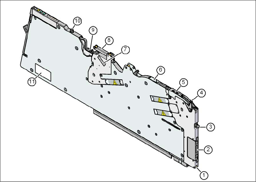
The two following diagrams show the design of the tape feeder module for the X-Series with ref-
erence to the 8 mm X tape feeder module.
3
Fig. 3.9 - 1 8 mm X tape feeder module - front view
(1) Locking roller (the locking latch of the changeover table locks the feeder module in its end
position with the locking roller.)
(2) EDIF (energy and data interface)
(3) "Front" centering pin
(4) Lever for raising the pick-up window in order to thread in and remove the component tape
(5) Pickup window
(6) Tape guide channel outlet
(7) Setting the cover foil tension
(8) Cover foil rocker
(9) Cover foil packing wheels
(10) "Back" centering pin
(11) Typeplate
User manual SIPLACE SX1/SX2 3 Technical data and assemblies
From software version SC 706.1 SP1 Version 10/2014 3.9 X feeder modules for SIPLACE SX1/SX2
147
3
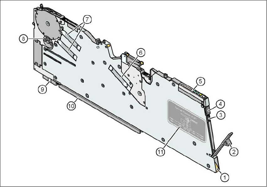
Fig. 3.9 - 2 8 mm X tape feeder module - back view
(1) Entry to the tape guide channel with tape spring
(2) Flap on cover foil container
(3) Integrated blade for cutting off the cover foil
(4) Removal handle, engaged
(5) Operator panel
(6) Drive motor for the cover foil packing device
(7) Drive motors for the tape conveyor
(8) Rotary valve for removing components
(9) Front slider guide
(10) Back slider guide
(11) Graphical representation of the pick-up position in relation to the component size