00196962-04-BA-SX12-V2-EN.pdf - 第271页
User manual SIPLACE SX1/SX2 5 Working with the machine From software version SC 706.1 SP1 Version 10/2014 5.11 Observing displays on the X feeder module 271 5.1 1.2 Feeder module with LED display The SIPLACE SmartFeeder …
5 Working with the machine User manual SIPLACE SX1/SX2
5.11 Observing displays on the X feeder module From software version SC 706.1 SP1 Version 10/2014
270
5.11 Observing displays on the X feeder module
5.11.1 Feeder module with LCD display
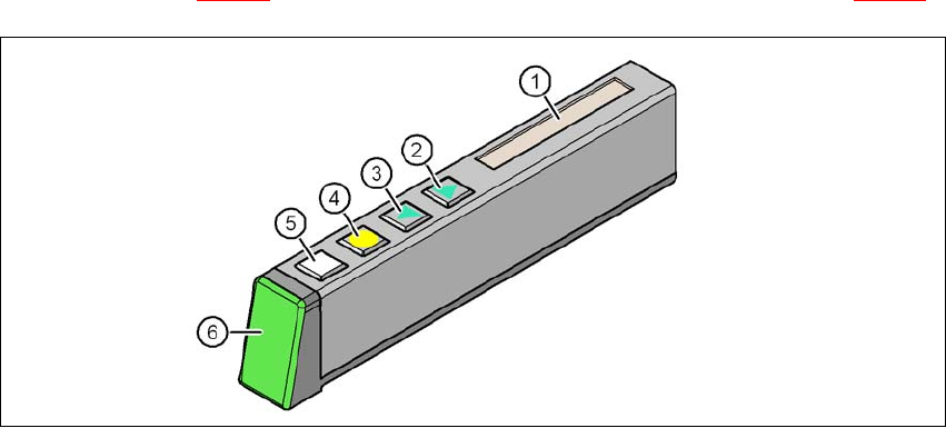
The X feeder modules (8 mm to 88 mm) have a multicolored status display to indicate operating
states (item 6 in fig. 5.11 - 1
) and for showing the texts on an LCD display (item 1 in fig. 5.11 - 1).
5
Fig. 5.11 - 1 Buttons, LCD and status displays on the X feeder module
(1) LCD display
(2) FORWARD button
(3) BACK button
(4) FOIL button
(5) SET button
(6) Status display, multicolor
User manual SIPLACE SX1/SX2 5 Working with the machine
From software version SC 706.1 SP1 Version 10/2014 5.11 Observing displays on the X feeder module
271
5.11.2 Feeder module with LED display
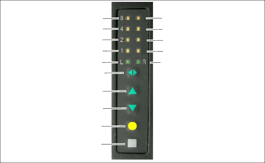
The SIPLACE SmartFeeder have a multicolored LED status display for each track, to indicate the
operating states.
5
Fig. 5.11 - 2 Buttons and status displays: Example of SIPLACE SmartFeeder 2x8 mm
(1) SET button
(2) FOIL button
(3) BACK button
(4) FORWARD button
(5) Track change button for switching between right and left
(6) LED L left track active
(7) LED 1 mm increment for left track
(8) LED 2 mm increment for left track
(9) LED 4 mm increment for left track
(10) LED 8 mm increment for left track
(11) LED R right track active
(12) LED 1 mm increment for right track
(13) LED 2 mm increment for right track
(14) LED 4 mm increment for right track
(15) LED 8 mm increment for right track
(1)
(2)
(3)
(4)
(5)
(6)
(7)
(8)
(9)
(10)
(15)
(14)
(13)
(12)
(11)
5 Working with the machine User manual SIPLACE SX1/SX2
5.11 Observing displays on the X feeder module From software version SC 706.1 SP1 Version 10/2014
272
5.11.3 Status display
–Green:
The feeder module is on standby and is contained in the current setup.
– Orange:
A warning is being signalized. The text of the warning appears on the LCD display.
– Red:
A malfunction has occurred. The error message is output on the LCD display.
–Off:
The feeder module is not in the current setup.
5
5
PLEASE NOTE
"LED off" only for feeder modules contained in the setup
The machine controller switches off the status display of any feeder modules not included
in the setup.
The "LED off" status only occurs when the programming system has preset a job on the
line. This takes some of the work away from the operator since he only has to watch those
feeder modules that are contained in the setup.
PLEASE NOTE
Setup procedure: Activation of LED for each feeder module
For the actual setup process - no setup information at the station, no job sent from SI-
PLACE Pro to the station/line - the LED on each feeder module is activated after the setup
has been made. The operator is thus informed whether everything is OK.