00196962-04-BA-SX12-V2-EN.pdf - 第333页
User manual SIPLACE SX1/SX2 6 Station extensions From software version SC 706.1 SP1 Version 10/2014 6.7 Sensor for the component reject bin 333 6.6.4 W arning label 206 6 – W206 in fig. 6.6 - 4 , page 332 , item no. 0300…
6 Station extensions User manual SIPLACE SX1/SX2
6.6 Docking station for the component trolley of the SIPLACE SX From software version SC 706.1 SP1 Version 10/2014
332
6.6.3 Warning labels on the docking station
6
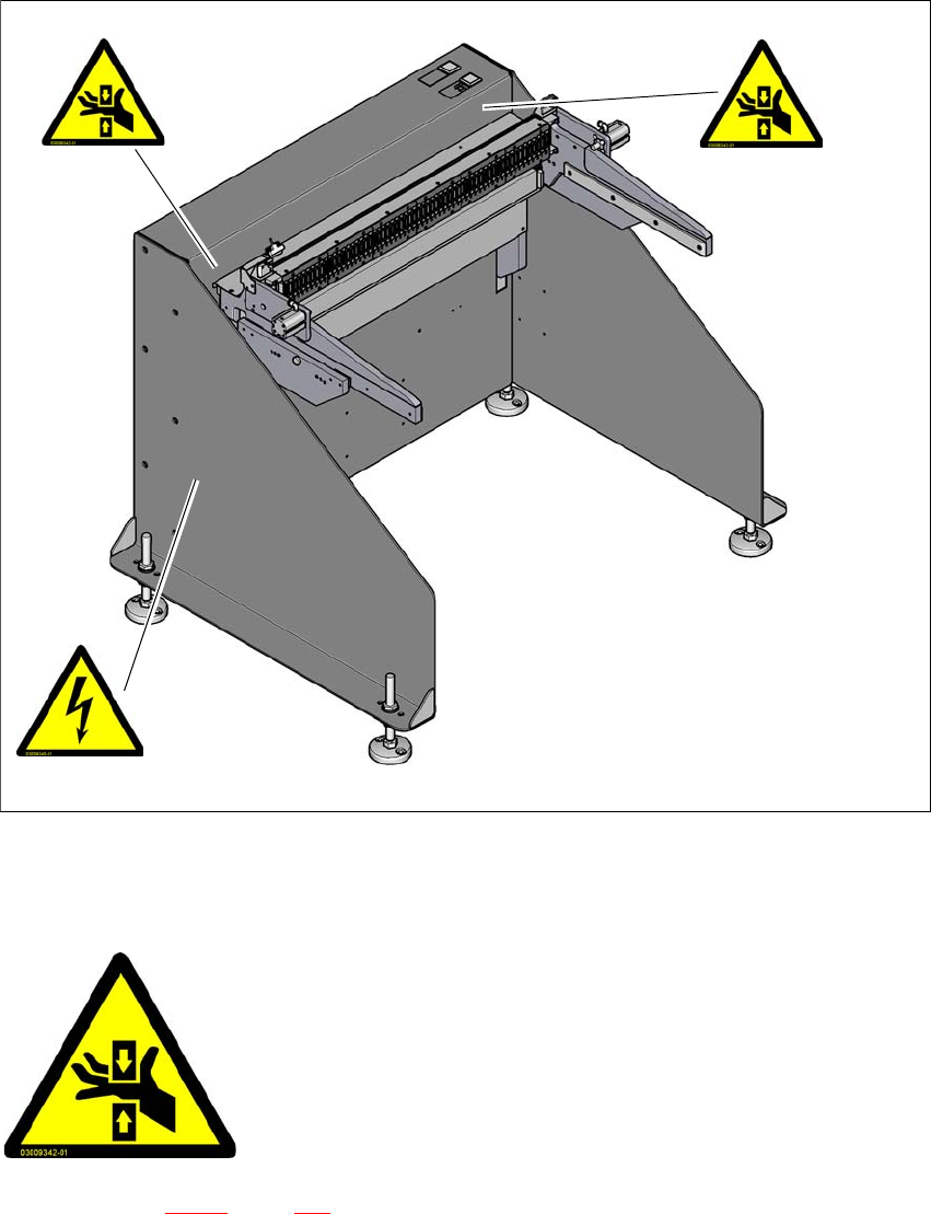
Fig. 6.6 - 4 Docking station, SIPLACE SX-Series - warning labels
6.6.3.1 Warning label W203
6
– W203 in fig. 6.6 - 4, page 332, item no. 03009342-01
– 2x on the docking station for SIPLACE SX component trolley
– 1x each on the left and right, behind the energy and data interface on the housing.
W 203
W 203
W206
6
6
6
DANGER OF CRUSHING!
Reaching in here can lead to injuries to the arms
and hands.
Do not reach into the machine while it is running
User manual SIPLACE SX1/SX2 6 Station extensions
From software version SC 706.1 SP1 Version 10/2014 6.7 Sensor for the component reject bin
333
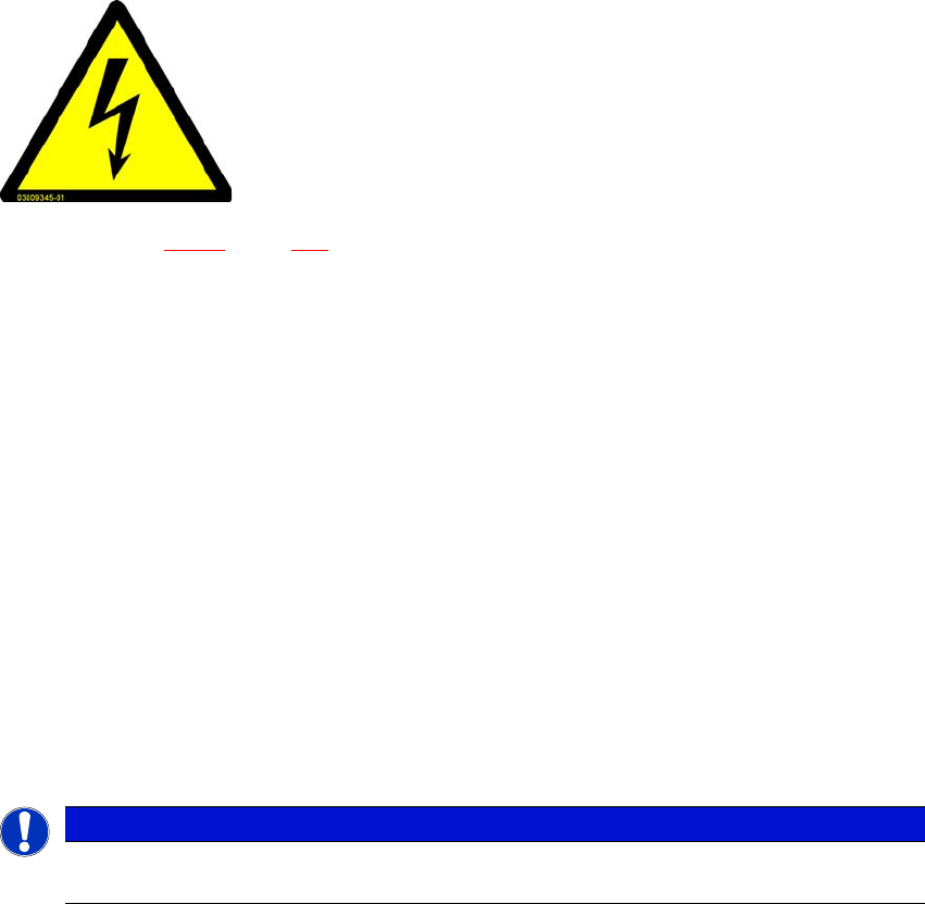
6.6.4 Warning label 206
6
– W206 in fig. 6.6 - 4, page 332, item no. 03009345-01
– 1x on the docking station for SIPLACE SX component trolley
– 3 x on the covers for the energy supply.
6.7 Sensor for the component reject bin
Item no. 00519848-xx query for component reject bin
The sensor for the component reject bin monitors whether the reject bin is seated correctly in its
mount.
– If the reject bin was not inserted correctly, the machine cannot be started.
– If the reject bin jumps out of its mount during the placement process, the machine is stopped
immediately to avoid a head crash.
Each reject bin can be monitored by a separate sensor.
6
DANGEROUS VOLTAGES!
The labeled parts are still live when the main power switch is off.
Disconnect the machine from the mains before servicing it.
NAFTA region: RISK OF ELECTRIC SHOCK OR BURN!
PLEASE NOTE
When using a SpeedStar we recommend that you install the optional sensor for the com-
ponent reject bin.

6 Station extensions User manual SIPLACE SX1/SX2
6.8 SIPLACE High-Force Head From software version SC 706.1 SP1 Version 10/2014
334
6.8 SIPLACE High-Force Head
Item no. 00119736-xx High-Force Head
6.8.1 Description
The SIPLACE high force head can process the same component range and also offers the pos-
sibility of achieving set-down forces up to 30 N. The SIPLACE high force head can use all the
same nozzles and grippers as the standard TwinStar.
6.8.2 Technical data
6
All other technical data are identical for the SIPLACE TwinStar and SIPLACE high force head (see
section 3.5.5.2
, page 123).
Programmable set-down force 2.0 N to 10 N ± 10 %
greater than 10 N up to 30 N ± 15 %