00196962-04-BA-SX12-V2-EN.pdf - 第126页
3 Technical data and assemblies User manual SIPLACE SX1/SX2 3.6 Gantry system From software version SC 706.1 SP1 Version 10/2014 126 3 Fig. 3.6 - 3 Design of X axis - view of head mount (1) Y linear moto r 1 with loose b…
User manual SIPLACE SX1/SX2 3 Technical data and assemblies
From software version SC 706.1 SP1 Version 10/2014 3.6 Gantry system
125
3.6.2 X axis structure
3
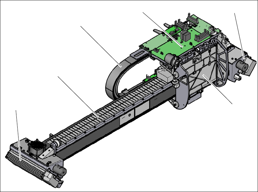
Fig. 3.6 - 2 Design of X axis - view of head mount
(1) Head mount with X axis linear motor (primary part)
(2) Y linear motor 2 with fixed bearing (primary part) and fan
(3) Guidance system with permanent magnet (secondary part of the X linear motor)
(4) Trailing cable
(5) Head board with Head Control Unit
(6) Y linear motor 1 with loose bearing (primary part) and fan
(4)
(3)
(1)
(5)
(2)
(6)
3 Technical data and assemblies User manual SIPLACE SX1/SX2
3.6 Gantry system From software version SC 706.1 SP1 Version 10/2014
126
3
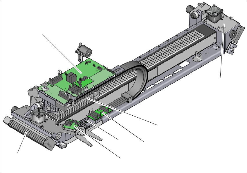
Fig. 3.6 - 3 Design of X axis - view of head mount
(1) Y linear motor 1 with loose bearing (primary part) and fan
(2) Head board with Head Control Unit
(3) Y linear motor 2 with loose bearing (primary part) and fan
(4) X axis linear motor (primary part)
(5) Gantry interface X axis
(6) Gantry interface Y axis
(7) Sensor module
(2)
(1)
(3)
(4)
(5)
(7)
(6)
User manual SIPLACE SX1/SX2 3 Technical data and assemblies
From software version SC 706.1 SP1 Version 10/2014 3.6 Gantry system
127
3
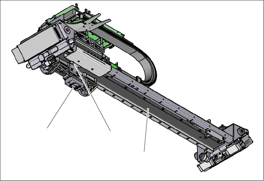
Fig. 3.6 - 4 Design of X axis - view from below
(1) PCB camera
(2) Incremental encoder
(3) Length measurement system (on the gantry underside)
The X axis is driven by a linear motor. The secondary part of the drive consists of a permanent
magnet and is mounted on the gantry arm. The primary part is bolted to the head mount. The head
mount has been designed so that all placement head types can be accommodated - one of the
benefits of the great flexibility in the SIPLACE machines.
(2)
(1)
(2)
(3)