00196962-04-BA-SX12-V2-EN.pdf - 第336页
6 Station extensions User ma nual SIPLACE SX1/SX2 6.9 SIPLACE Very High Force TwinStar (VHF TH) From software version SC 706.1 SP1 Version 10/2014 336 6.9.2 Overview 6 Fig. 6.9 - 1 SIPLACE Very High Force T winS tar (VHF…

User manual SIPLACE SX1/SX2 6 Station extensions
From software version SC 706.1 SP1 Version 10/2014 6.9 SIPLACE Very High Force TwinStar (VHF TH)
335
6.9 SIPLACE Very High Force TwinStar (VHF TH)
Item no. 00519986-xx VHF TwinStar with gantry
6
6.9.1 Description
The SIPLACE Very High Force TwinStar is an advanced development of the standard TwinStar.
The SIPLACE Very High Force TwinStar is suitable for processing complex and large compo-
nents.
It can process components up to a height of 40 mm and also offers the possibility of achieving set-
down forces up to 70 N. The SIPLACE Very High Force TwinStar can use all the same nozzles
and grippers as the standard TwinStar.
For a detailed description, refer to the "Assembly Instructions - Head Reconfiguration Kit VHF
head", Item No. 00197270-xx]
PLEASE NOTE
Available from software version SC.707.1
6 Station extensions User manual SIPLACE SX1/SX2
6.9 SIPLACE Very High Force TwinStar (VHF TH) From software version SC 706.1 SP1 Version 10/2014
336
6.9.2 Overview
6
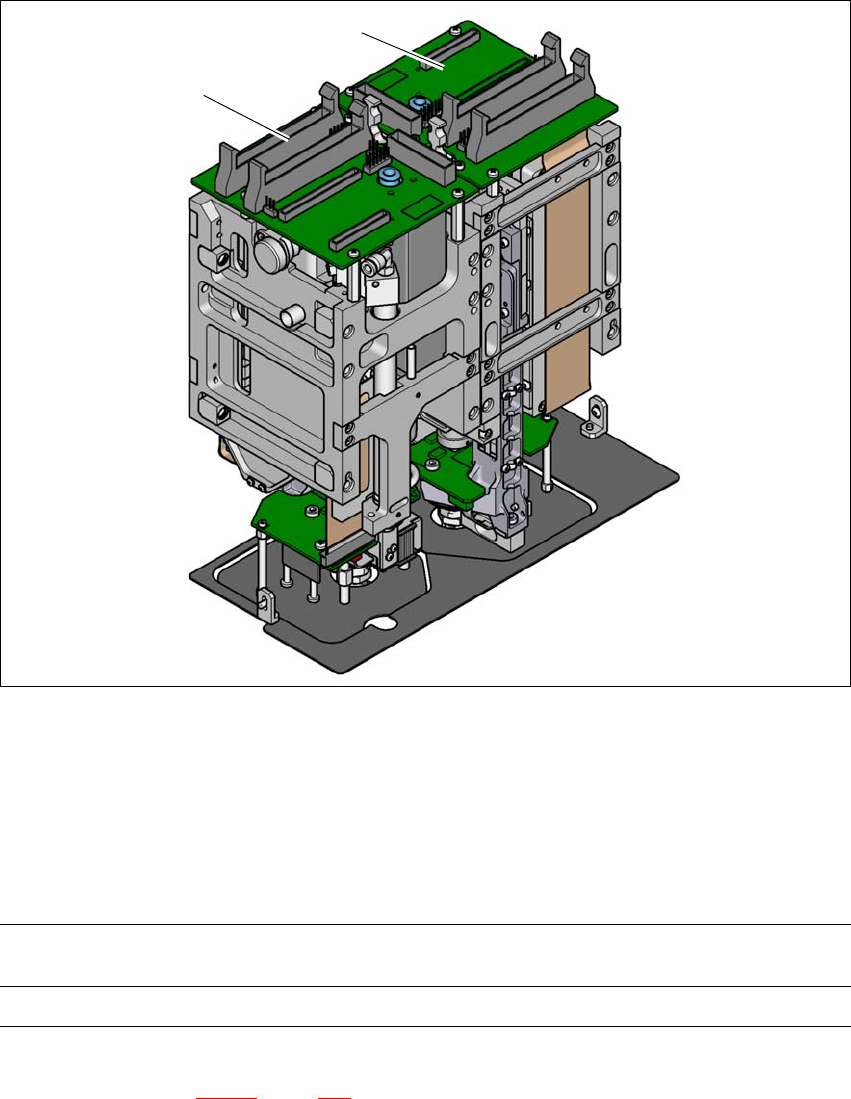
Fig. 6.9 - 1 SIPLACE Very High Force TwinStar (VHF TH)
(1) Pick&Place module 1 (P&P1)
(2) Pick&Place module 2 (P&P2)
6.9.3 Technical data
6
All other technical data are identical for the SIPLACE TwinStar and SIPLACE Very High Force
TwinStar (see section 3.5.5.2
, page 123).
2
1
Programmable set-down force
1.0 N - 15 N
2.0 N - 70 N
Max. component height 40 mm

User manual SIPLACE SX1/SX2 6 Station extensions
From software version SC 706.1 SP1 Version 10/2014 6.10 SIPLACE 12 segment Collect&Place head
337
6.10 SIPLACE 12 segment Collect&Place head
Item no. 00119820-xx C&P12 head
6
6.10.1 Description
The 12 segment Collect&Place head operates according to the Collect&Place principle i.e. one
cycle includes pickup of 12 components by
the placement head, their optical centering on the way to the placement position and their rotation
into the required placement angle and position. They are then placed gently and accurately onto
the PCB with a blast of air. In contrast to the conventional chip shooters, the twelve nozzles of the
Collect&Place heads rotate around a horizontal axis. This not only saves space: the reduced di-
ameter leads to a lower formation of centrifugal forces than in chip shooters. This largely prevents
any unintentional displacement of components during transportation.
Another benefit: the Collect&Place head has the same cycle time for all components. This means
that the placement performance no longer depends on the size of the components placed.
PLEASE NOTE
Available from software version SC.707.1 and on request