00196962-04-BA-SX12-V2-EN.pdf - 第226页
5 Working with the machine User manual SIPLACE SX1/SX2 5.1 Staff profiles From software version SC 706.1 SP1 Version 10/2014 226 5.1.3 Operator level "Service (customer)" 5.1.3.1 T asks The service pers onnel&a…
User manual SIPLACE SX1/SX2 5 Working with the machine
From software version SC 706.1 SP1 Version 10/2014 5.1 Staff profiles
225
5.1.2 Operator level "Advanced production"
5.1.2.1 Tasks
The line engineers should be assigned the following tasks:
– Acting as a contact for the operators
– Maintaining the machine log book
– Monitoring and carrying out preventive maintenance at the specified intervals
– Monitoring the workplace to ensure that it is clean and safe
– Monitoring conformity with ESD regulations
– Carrying out quality control
– Following up and reporting fault messages
– Making sure that errors have been eliminated
– Providing all materials required to produce the job in a timely manner, such as
–PCBs
– splicing materials
– Soldering paste
– Components
– Feeder modules, etc.
– Setting up the station for a new production batch
– Checking the feeder module settings:
– Increment
– Pickup position
– Checking the management data
– Checking the management data from MaDaMaS or OIS
– Asking the responsible programmers to modify placement programs
– Ensuring a smooth flow of information between the individual groups
5 Working with the machine User manual SIPLACE SX1/SX2
5.1 Staff profiles From software version SC 706.1 SP1 Version 10/2014
226
5.1.3 Operator level "Service (customer)"
5.1.3.1 Tasks
The service personnel's duties include:
– Major preventive maintenance jobs
– Mounting replacement parts
– Editing machine data
– Calibrating the machine
5.1.4 Operator level "Service (SIPLACE)"
5.1.4.1 Tasks
The programmer's jobs are as follows:
– Preparing CAD files
– Creating and calibrating vision data (teaching)
– Writing placement programs
– Implementing a new job
– Data maintenance
– Data backup
User manual SIPLACE SX1/SX2 5 Working with the machine
From software version SC 706.1 SP1 Version 10/2014 5.2 Controls and displays
227
5.2 Controls and displays
5.2.1 Overview
5
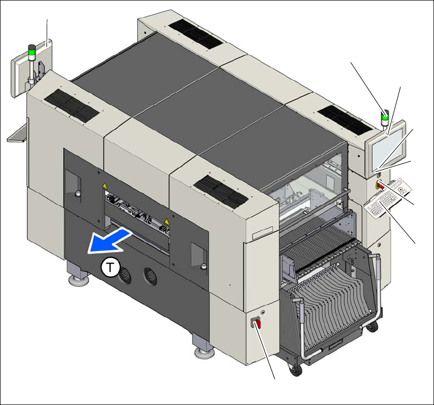
Fig. 5.2 - 1 Controls and displays
5
(1) Main switch (5) Start button
(2) Stop button (black) (6) LCD touchscreen
(3) EMERGENCY STOP button (7) Indicator lamps with horn
(4) Keyboard (T) Direction of PCB transport
(1)
(4)
(3)
(2)
(6)
(7)
(7)
(5)