00196962-04-BA-SX12-V2-EN.pdf - 第176页
3 Technical data and assemblies User manual SIPLACE SX1/SX2 3.10 Component trolley for SIPLACE SX1/SX2 From software version SC 706.1 SP1 Version 10/2014 176 3.10.4 Dimensions of th e component trolley 3 Fig. 3.10 - 5 Di…
User manual SIPLACE SX1/SX2 3 Technical data and assemblies
From software version SC 706.1 SP1 Version 10/2014 3.10 Component trolley for SIPLACE SX1/SX2
175
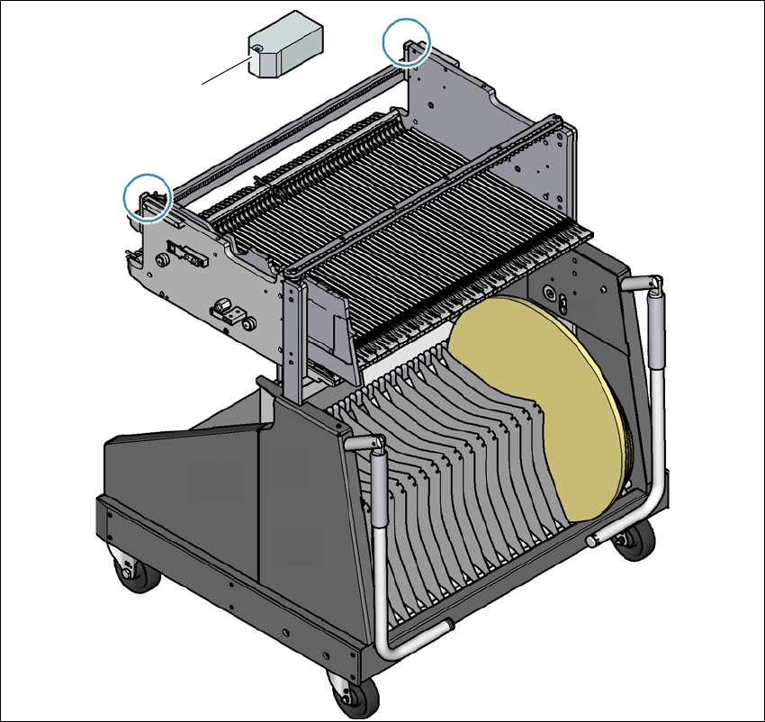
3.10.3 Fiducials on the component trolley
3
Fig. 3.10 - 4 Fiducials on the component trolley
(1) Fiducials on the component trolley
Once the SIPLACE component trolley has been docked in, the machine measures the
fiducials on the component trolley.
For components with an edge length of less than 0.5 mm, i.e. 0402 components and smaller, the
position of the component is determined with the tape pocket before the first component is picked
up.
(1)
3 Technical data and assemblies User manual SIPLACE SX1/SX2
3.10 Component trolley for SIPLACE SX1/SX2 From software version SC 706.1 SP1 Version 10/2014
176
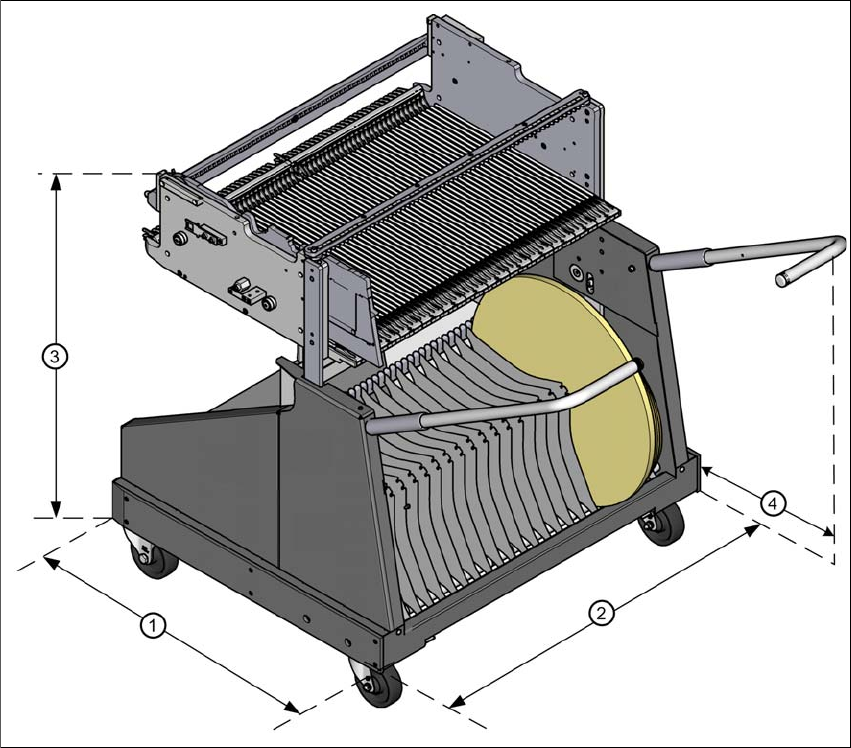
3.10.4 Dimensions of the component trolley
3
Fig. 3.10 - 5 Dimensions of the component trolley, SIPLACE SX1/SX2, all dimensions in millimeters
(1) Length = 760 mm
(2) Width = 864 mm
(3) Height (depends on the height setting
– For 900 mm = 934 mm
– For 930 mm = 964 mm
– For 950 mm = 984 mm
(4) Distance between handles when folded open = 476 mm
User manual SIPLACE SX1/SX2 3 Technical data and assemblies
From software version SC 706.1 SP1 Version 10/2014 3.10 Component trolley for SIPLACE SX1/SX2
177
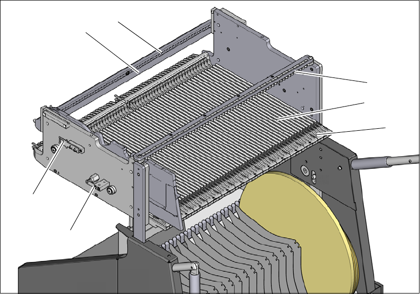
3.10.5 Changeover table for SIPLACE SX1/SX2
The front slider guides of the feeder modules are placed on the insertion aid. As it is pushed in,
the guides of the feeder module slide on the guide profile as far as the stop bar. A centering hole
on the stop bar holds the "front" centering pin of the X feeder module. At the same time, the locking
latch of the changeover table latches onto the locking roller of the feeder module. The "back" cen-
tering pin on the top of the feeder module is held by the recess in the centering bar.
3
Fig. 3.10 - 6 Changeover table, back view
(1) Insertion aid
(2) Guide profile (Ω profile)
(3) Centering bar for holding the "back" centering pin for X feeder modules
(4) Stop bar
(5) Centering holes
(6) Contact for switching the safety switch of the EMERGENCY STOP circuit
(7) Lock
(1)
(2)
(3)
(4)
(5)
(6)
(7)