00196962-04-BA-SX12-V2-EN.pdf - 第297页
User manual SIPLACE SX1/SX2 6 Station extensions From software version SC 706.1 SP1 Version 10/2014 6.1 Nozzle changer 297 6.1.2.3 Position of nozzle changer for th e SIPLACE MultiSt ar in the SX machine 6 Fig. 6.1 - 9 P…
6 Station extensions User manual SIPLACE SX1/SX2
6.1 Nozzle changer From software version SC 706.1 SP1 Version 10/2014
296
Nozzle magazine for 28xx nozzles 6
– Item no. 03065782-xx
6
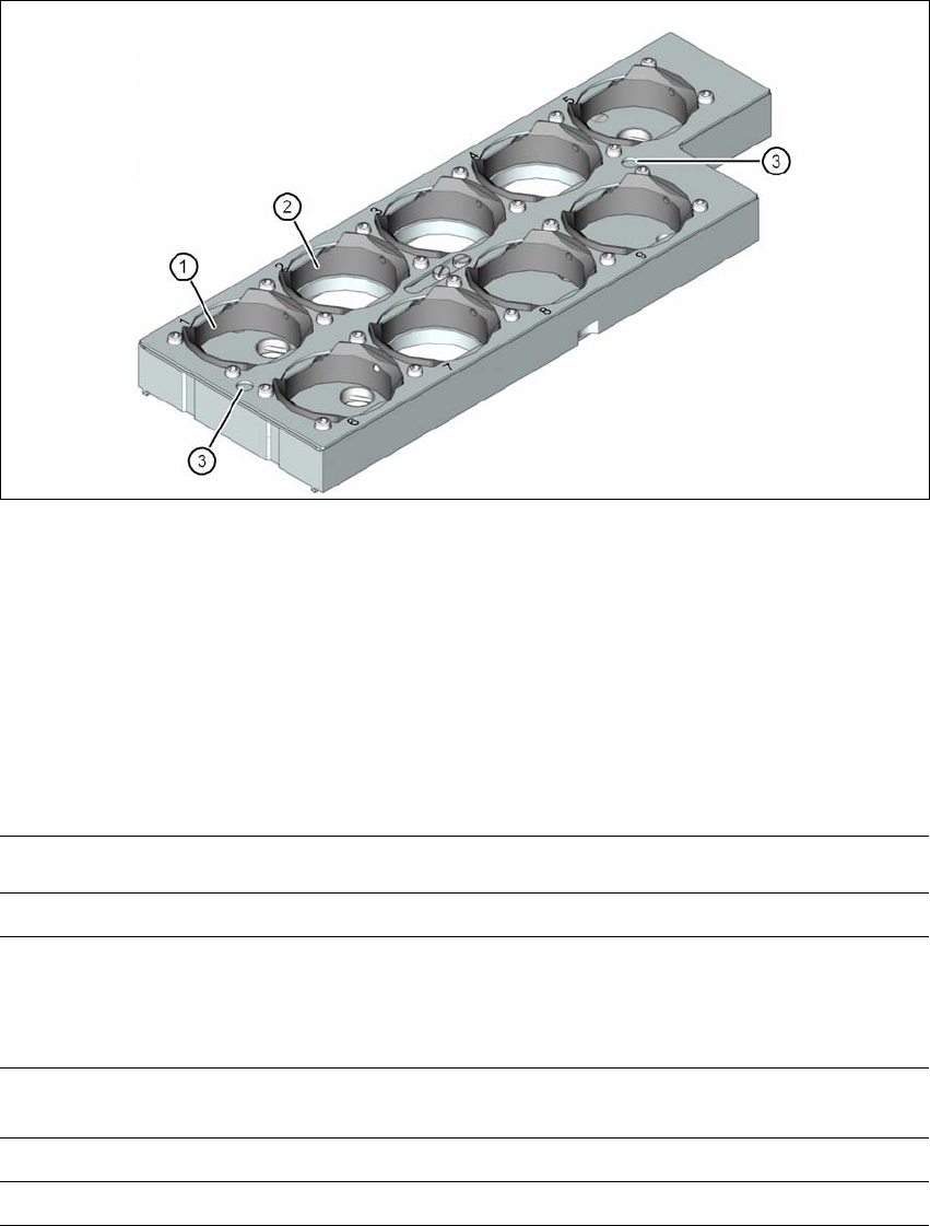
Fig. 6.1 - 8 Nozzle magazine for 28xx nozzles
(1) 5 garages for 28xx nozzles with a maximum nozzle length of 12.5 mm
(garage numbers 1, 5, 6, 8 and 9)
(2) 4 garages for 28xx nozzles with a maximum nozzle length of 20.0 mm
(garage numbers 2, 3, 4 and 7)
(3) Fiducials (only visible when locking plate open)
6.1.2.2 Technical data
6
Nozzle changer for the SIPLACE MultiStar
Dimensions (length x width x height) 314 mm x 94.5 mm x 72.25 mm
Number of nozzle holders
Type 20xx 36
Type 28xx 9
Nozzle types (standard configuration)
*a
*)a The number of nozzle magazines can be adjusted where necessary (e.g. 4 x 28xx)
3 magazines with 20xx nozzles
1 magazine with 28xx nozzles
Nozzle changeover time Approx. 2s per nozzle
Compressed air connection 0.45 MPa (4.5 bar)
User manual SIPLACE SX1/SX2 6 Station extensions
From software version SC 706.1 SP1 Version 10/2014 6.1 Nozzle changer
297
6.1.2.3 Position of nozzle changer for the SIPLACE MultiStar in the SX machine
6
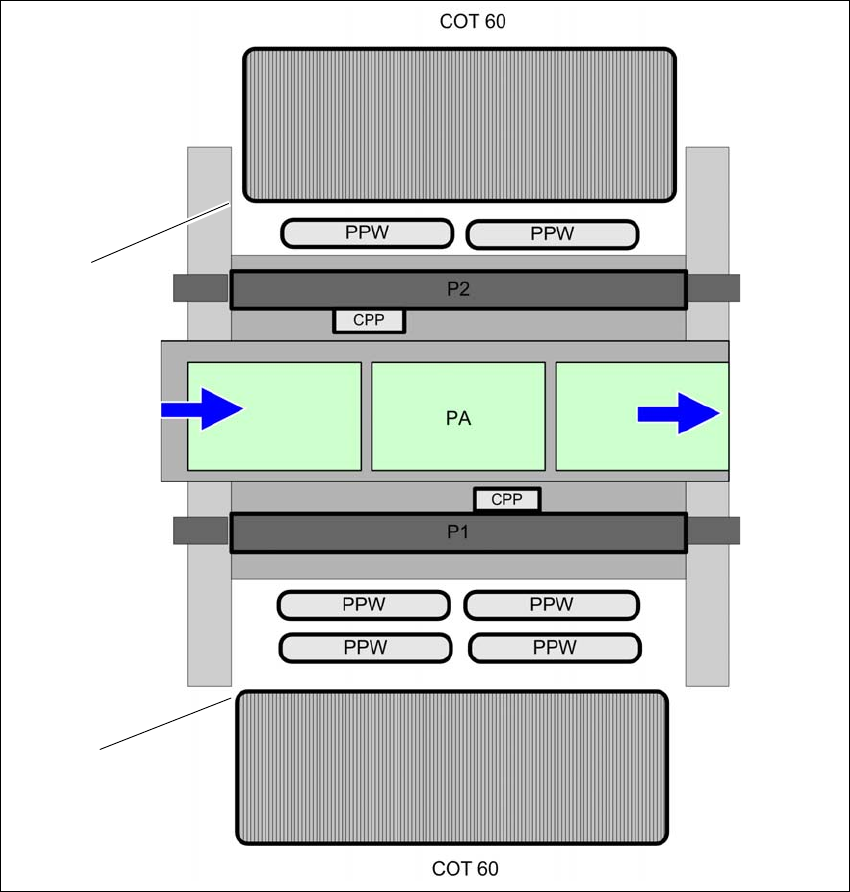
Fig. 6.1 - 9 Position of nozzle changer for the SIPLACE MultiStar - example
6
(1) Component trolley in the inner position
(2) Component trolley in the outer position
(NC) Nozzle changer
(PA) Placement area
(1)
(2)
6 Station extensions User manual SIPLACE SX1/SX2
6.1 Nozzle changer From software version SC 706.1 SP1 Version 10/2014
298
6.1.2.4 Assembly
In SX machines, the nozzle changers are fixed to the component trolley COT insert. Other nozzle
changers can also be installed.
6
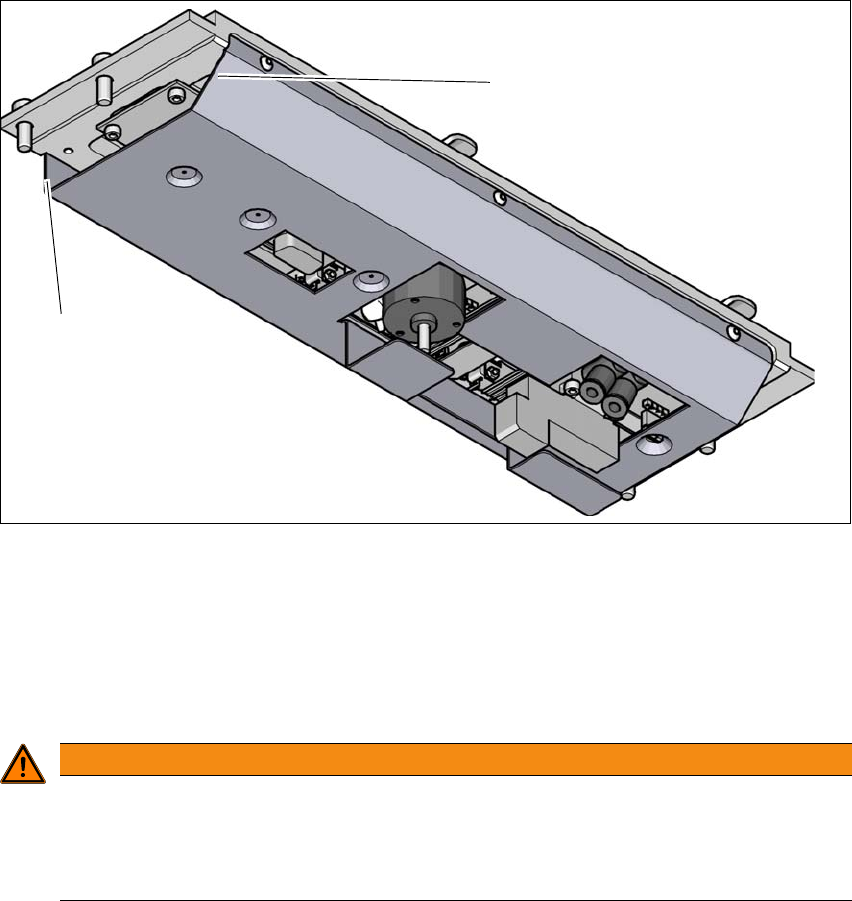
Fig. 6.1 - 10 Assembly position of nozzle changer - view from below
(1) Sloping side points towards the component trolley COT insert
(2) Vertical side points towards the PCB conveyor
Align the nozzle changer so that the sloping side points towards the component trolley COT
insert.
6
WARNING
Risk of head crashes with mixed configurations!
There is a risk of head crashes with mixed configurations.
Only install the associated nozzle changer for each placement head, with the nozzle
magazines for the respective placement head.
(1)
(2)