00196962-04-BA-SX12-V2-EN.pdf - 第171页
User manual SIPLACE SX1/SX2 3 Technical data and assemblies From software version SC 706.1 SP1 Version 10/2014 3.10 Component trolley for SIPLACE SX1/SX2 171 3.10 Component trolley for SIPLACE SX1/SX2 Item no. 00519922-x…

3 Technical data and assemblies User manual SIPLACE SX1/SX2
3.9 X feeder modules for SIPLACE SX1/SX2 From software version SC 706.1 SP1 Version 10/2014
170
3.9.6.1 Description
The energy and data interface allows X feeder modules to be used outside the machine and setup
area. The interface consists of an aluminum frame with omega profile (item 7 in fig. 3.9 - 18
, page
167
) for holding and guiding the feeder modules. As with the X component trolley, the feeder mod-
ule is placed on the omega profile, with the slider guides, and is pushed forwards until the front
centering pin of the feeder module is fully inserted into the locating hole (item 9 in fig. 3.9 - 18
,
page 167
). The locking latch (item 8 in fig. 3.9 - 18, page 167) locks the feeder module in this po-
sition. To remove the feeder module, simply press the release button (item 1 in fig.
3.9 - 18
, page 167 ). The locking latch (item 8 in fig. 3.9 - 18, page 167) is pressed down and re-
leases the feeder module. Fold-out feet (item 6 in fig. 3.9 - 18
, page 167) stabilize the position of
the energy and data interface, particularly for wide feeder modules.
The electronic housing (item 5 in fig. 3.9 - 18
, page 167) holds the electronic control unit for the
energy and data interface. The operator panel (item 2 in fig. 3.9 - 18
, page 167) consists of start
and stop buttons and two status LEDs. Communication with a PC takes place via the data cable
(item 3 in fig. 3.9 - 18
, page 167 ). The power supply cable (item 4 in fig. 3.9 - 18, page 167) is
connected to the power supply unit provided.
3.9.6.2 Usage
The energy and data interface is used to check, maintain and repair X feeder modules. It can also
be used for setting up in advance for PCB production. In this case, the energy and data interface
is fixed to the base plate (item 10 in fig. 3.9 - 20
, page 169). The tape reel holder (item 11 in fig.
3.9 - 20
, page 169) is also mounted on the base plate. When a component tape is inserted, you
can check or reset the increment, pick-up position and conveyor speed. The detailed user manual
describes how to use the interface and the necessary servicing work.
3.9.6.3 Scope of delivery
– Single Slot EDIF
– Power supply, 100 - 120 / 200 - 240 VAC, +30VDC, 4.3 A
– Base plate with tape reel arm
– User manual
User manual SIPLACE SX1/SX2 3 Technical data and assemblies
From software version SC 706.1 SP1 Version 10/2014 3.10 Component trolley for SIPLACE SX1/SX2
171
3.10 Component trolley for SIPLACE SX1/SX2
Item no. 00519922-xx Component trolley for SIPLACE SX1/SX2 with 60 tracks
Item no. 00519722-xx Component trolley for SIPLACE SX1/SX2 with 30 tracks
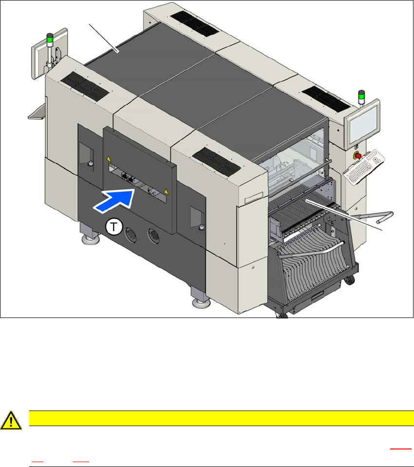
The SIPLACE SX1/SX2 machines can accommodate two SIPLACE SX1/SX2 component trolleys,
each with 60 tracks. If a WPC5/WPC6 is set up at one of the locations, the other location can ac-
commodate a component trolley with 30 tracks.
3
Fig. 3.10 - 1 Component trolley locations, SIPLACE SX1/SX2
(1) Location 1
(2) Location 2
(T) Direction of PCB transport
3
CAUTION
The SIPLACE SX1/SX2 component trolleys may only be docked onto locations at which
the component trolley COT insert for the SIPLACE SX1/SX2 has been installed (fig. 5.15
- 4, page 282 ).
(2)
(1)
3 Technical data and assemblies User manual SIPLACE SX1/SX2
3.10 Component trolley for SIPLACE SX1/SX2 From software version SC 706.1 SP1 Version 10/2014
172
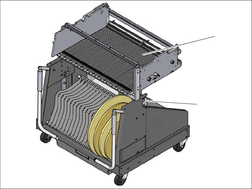
The component trolleys are stand-alone modules that can be set up with feeders at an external
setup area. This means that the production process only has to be interrupted briefly in order to
change the component trolley.
3
Fig. 3.10 - 2 Component trolley, SIPLACE SX1/SX2
(1) Changeover table with 60 tracks
(2) Height setting for fine adjustment to the machine height
3.10.1 Structure
The component trolley essentially consists of the chassis, the changeover table for holding the
feeder modules, the tape reel container and the waste tape container. There are two different com-
ponent trolleys available. One component trolley has a changeover table with 60 tracks and the
other one has a changeover table with 30 tracks. The component trolley with 30 tracks must be
set up next to the WPC5/WPC6.
(2)
(1)