00196962-04-BA-SX12-V2-EN.pdf - 第138页
3 Technical data and assemblies User manual SIPLACE SX1/SX2 3.8 Vision system From software version SC 706.1 SP1 Version 10/2014 138 3.8 V ision system 3.8.1 S tructure A component camera is integ rated at each Collect&a…
User manual SIPLACE SX1/SX2 3 Technical data and assemblies
From software version SC 706.1 SP1 Version 10/2014 3.7 PCB conveyor system
137
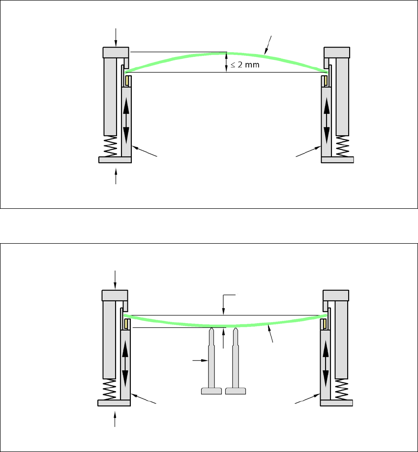
3.7.5.2 PCB warpage during placement
A warpage of 2 mm can lead to problems focussing on local fiducials and ink spots in the middle
of the PCB. The digital camera's focus is 2 mm. When all the tolerances are taken into account,
this value is reduced to 1.5 mm. Also note that the component height is reduced by the warpage.
3
3
PCB warpage down, max. 0.5 mm
3
Use magnetic pin supports to achieve this value.
Movable clamping device
Fixed clamped edge
Printed circuit board
Conveyor side wall
Printed circuit board
Magnetic pin
support
Movable clamping device
Fixed clamped edge
Conveyor side wall
0.5 mm

3 Technical data and assemblies User manual SIPLACE SX1/SX2
3.8 Vision system From software version SC 706.1 SP1 Version 10/2014
138
3.8 Vision system
3.8.1 Structure
A component camera is integrated at each Collect&Place head (see fig. 3.5 - 2 page 107 and fig.
3.5 - 4
page 112). The component camera, stationary, P&P (type 33) 55 x 45, digital, for the Mul-
tiStar and the TwinStar is fixed to the machine frame.
The component vision module is used to determine:
– the precise position of the components at the nozzle and
– the geometry of the package form.
The PCB vision module uses fiducials on the PCBs to determine:
– the position of the PCB,
– its rotation angle
– and the PCB skew.
The PCB cameras are fixed to the bottom of the gantries. They use fiducials on the feeder mod-
ules to determine the exact pick-up position of components, which is particularly important for
small components.
3
WARNING
Risk of head crash!
When changing the placement head from a TwinStar/VHF to a SpeedStar, the SpeedStar
collides with the camera housing.
Dismantle the stationary component cameras of type 33, 55 x 45, and type 25, 16 x
16 digital (FC camera) for the TwinStar.
When changing the placement head from TwinStar to MultiStar, the stationary component
camera, type 33, 55 x 45, digital, is fitted in the bottom position.
User manual SIPLACE SX1/SX2 3 Technical data and assemblies
From software version SC 706.1 SP1 Version 10/2014 3.8 Vision system
139
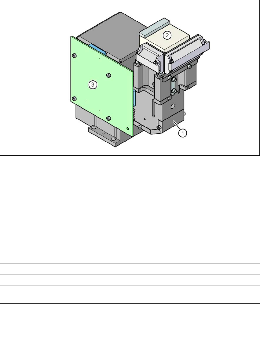
3.8.2 C&P component camera, type 30, 27 x 27, digital
3
Fig. 3.8 - 1 C&P component camera, type 30, 27 x 27, digital
(1) Component camera lens and illumination
(2) Camera amplifier
(3) Illumination control
3.8.2.1 Technical data
3
Component dimensions 0.3 mm x 0.3 mm to 27 mm x 27 mm
Component range 03015 to 27 mm x 27 mm
PLCC, SO, QFP, TSDP, SOT, MELF, CHIP, IC BGA
Min. lead pitch 0.3 mm
Min. lead width 0.15 mm
Min. ball pitch 0.25 mm for components < 18 mm x 18 mm
0.35 mm for components < ≥18 mm x 18 mm
Min. ball diameter 0.14 mm for components < 18 mm x 18 mm
0.2 mm for components < ≥18 mm x 18 mm
Field of vision 32 mm x 32 mm
Illumination type Front-illumination (5 levels, programmable as required)