00196962-04-BA-SX12-V2-EN.pdf - 第208页
4 Setting up and commissioning Us er ma nual SIPLACE SX1/SX2 4.3 Setting up the machine From software version SC 706.1 SP1 Version 10/2014 208 Insert the correct height adapter fo r the requ ired PCB conveyor height. …
User manual SIPLACE SX1/SX2 4 Setting up and commissioning
From software version SC 706.1 SP1 Version 10/2014 4.3 Setting up the machine
207
4
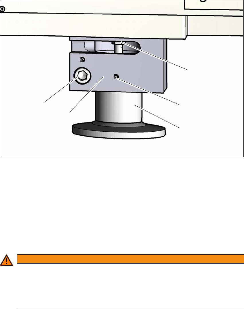
Fig. 4.3 - 4 Height adapter - adjusting the height
4
(1) Setting screw for adjusting the height
(2) Locking screw
(3) Height adapter
(4) Clamping
(5) Clamping screw
Loosen the locking screw (2). This locking screw fixes the height adapter and prevents it fall-
ing down as soon as the clamp has been loosened.
4
Loosen the clamping screw and pull the height adapter down and out.
Check the new height adapter to make sure that the height adjustment screw (1) can be
moved easily. If necessary, loosen the screw and grease the thread with Topas NCA 52.
To make sure that the height adapter can be easily pushed into the clamp (4), grease the
clamping area of the height adapter with Topas NCA 52.
WARNING
Risk of injuries!
After loosening the clamps, the height adapter could still fall out, despite being secured
with the grub screw in the groove, and could then injure hands and feet.
Hold the height adapter while fastening, to prevent it falling down.
Take care that your hands and feet can not be hit.
(3)
(1)
(2)
(4)
(5)

4 Setting up and commissioning User manual SIPLACE SX1/SX2
4.3 Setting up the machine From software version SC 706.1 SP1 Version 10/2014
208
Insert the correct height adapter for the required PCB conveyor height.
Push the height adapter into the clamp so that the notch engages with the locking screw (2).
Loosely tighten the locking screw (2).
Loosely tighten the clamping screw (5) so that the height adapter can be moved in the Z di-
rection with a minimum of play.
Fit the other 3 height adapters in the same manner.
Now use the fork-lift to carefully lower the machine until the height adapters touch the floor
evenly. There should always be a second person present to ensure that the machine remains
stable while it is being lowered. You may need to loosen the height adapter clamp slightly.
Use the SW 20 open double-ended ring spanner to adjust the height of each height adapter
at the setting screw, so that the relevant conveyor height is achieved.
Align the machine in the X and Y direction with the machine spirit level.
4
Tighten the clamping screw to a torque of 130 Nm.
PLEASE NOTE
For a description of how to align the machine in the X and Y directions, refer to the section
4.3.9
, page 213.
User manual SIPLACE SX1/SX2 4 Setting up and commissioning
From software version SC 706.1 SP1 Version 10/2014 4.3 Setting up the machine
209
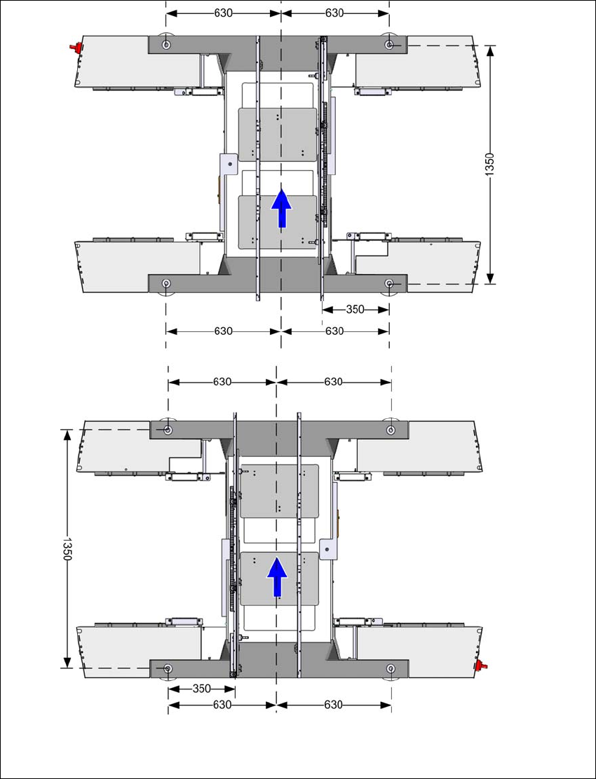
4.3.7 Machine foot clearances and the stationary PCB conveyor edges
4.3.7.1 Machine foot clearances for the PCB single conveyor
4
Fig. 4.3 - 5 Machine foot clearances for the PCB single conveyor in millimeters
Fixed conveyor side at maxi-
mum right position
a
.
Fixed conveyor side at
maximum left position
a
.
a) The value depends on the position of the fixed side.
All dimensions in millimeters.