00196962-04-BA-SX12-V2-EN.pdf - 第344页
6 Station extensions User ma nual SIPLACE SX1/SX2 6.12 Component camera for the MultiStar From software version SC 706.1 SP1 Version 10/2014 344 6.12.1.1 T echnical data 6 6 6.12.1.2 Position The position of the stationa…
User manual SIPLACE SX1/SX2 6 Station extensions
From software version SC 706.1 SP1 Version 10/2014 6.12 Component camera for the MultiStar
343
6.12 Component camera for the MultiStar
6.12.1 Component camera, stationary P&P, type 33, 55 x 45, digital
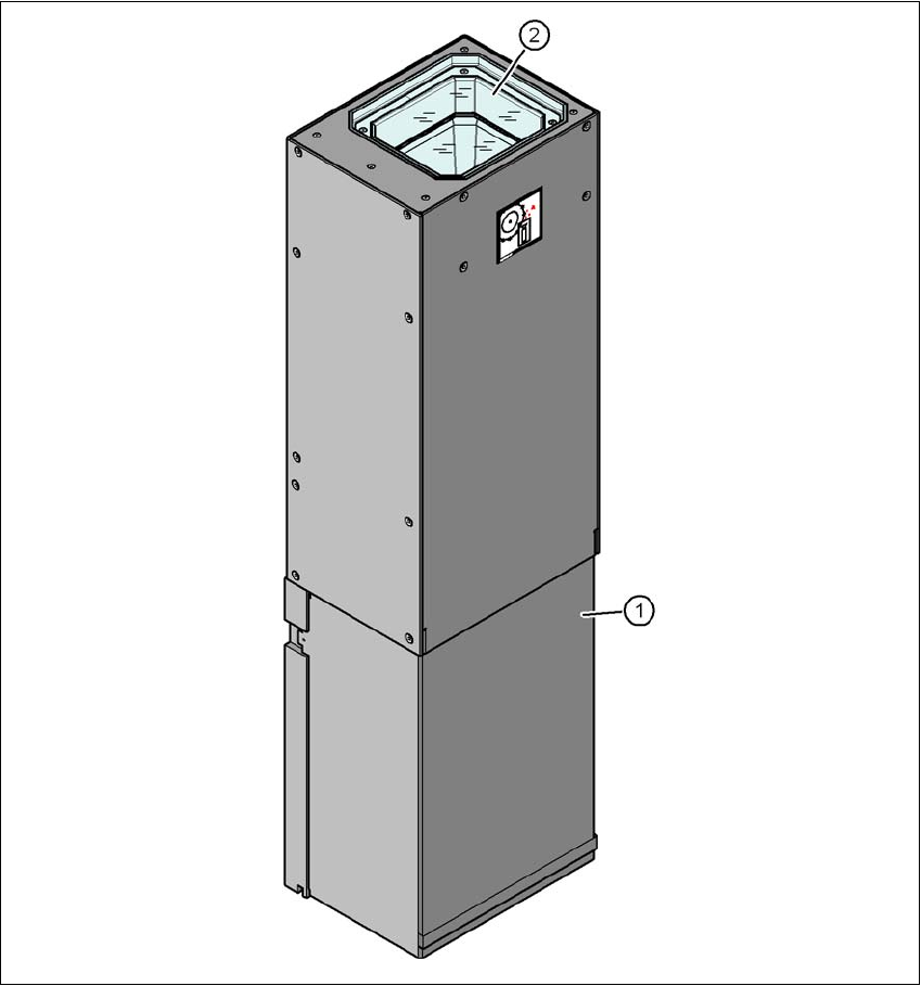
Item no. 00519902-xx Stationary camera for the CPP head, type 33
6
Fig. 6.12 - 1 Structure for the stationary P&P component camera, type 33, 55 x 45, digital
(1) Camera housing with integral camera and camera amplifier
(2) Glass plate - illumination and lens levels below

6 Station extensions User manual SIPLACE SX1/SX2
6.12 Component camera for the MultiStar From software version SC 706.1 SP1 Version 10/2014
344
6.12.1.1 Technical data
6
6
6.12.1.2 Position
The position of the stationary component cameras and the associated configurations are de-
scribed
in section 3.8.2
, from page 139.
Component dimensions 0.5 mm x 0.5 mm to 55 mm x 45 mm
Component range 0402, MELF, SO, PLCC, QFP, electrolytic capacitors, BGA
Min. lead pitch 0.3 mm
Min. lead width 0.15 mm
Min. ball pitch 0.35 mm
Min. ball diameter 0.2 mm
Field of vision 65 mm x 50 mm
Illumination type Front-illumination (6 levels, programmable as required)
User manual SIPLACE SX1/SX2 6 Station extensions
From software version SC 706.1 SP1 Version 10/2014 6.13 PCB alignment
345
6.13 PCB alignment
Item no. 00119677-xx PCB alignment, single conveyor
Item no. 00119678-xx PCB alignment, dual conveyor
6.13.1 Description
PCBs to be processed sometimes have a length to width ratio of 1:2 or worse. This means that
the shorter side of the PCB points in the direction of travel. During travel, such PCBs may twist
slightly and, as a result, the fiducials no longer lie within the PCB vision camera's search window.
In this case, the "PCB alignment" option ensures that these PCBs are realigned precisely at the
stopping position.
If PCBs with recesses in the direction of travel are processed, this may result in different process-
ing
positions on machines with mechanical stoppers and on machines that monitor this position with
laser light barriers. The "PCB alignment" option ensures that the PCBs are stopped at the same
position on all PCB conveyors. The "PCB alignment" option is available for both single and dual
conveyors.
The PCB is transported into the placement area until the laser light barrier triggers the stop signal
for the PCB conveyor. The lifting table with the PCB stops then moves up into a position in which
the PCB is not yet clamped and can still be moved by the conveyor belts. The two PCB stops are
level with the PCB, and the PCB supports (magnetic pins) are already in contact with the PCB.
The two conveyor belts move the PCB against the PCB stops and align them at the same time.
The lifting table then moves into its top end position, clamps the PCB and releases it from the PCB
stops so as not to affect the placement process. After the placement process, the lifting table and
PCB alignment are lowered and the PCB is moved on.
6.14 Siemens interface
Item no. 00116808-xx SIPLACE interface
The conveyor interface on the placement machines from the SX and X-Series is configured to the
SMEMA standard. It is, however, still possible to use this interface in accordance with the Siemens
standard. This is a significant benefit when an X-Series machine is to be integrated into older SI-
PLACE lines, in which case it would not be necessary to retrofit the older machines to conform to
the SMEMA standard.
Simply configure the conveyor interface of the SX-Series and X-Series machines to the Siemens
standard and connect the machines using the associated interface cable.