00196962-04-BA-SX12-V2-EN.pdf - 第125页
User manual SIPLACE SX1/SX2 3 Technical data and assemblies From software version SC 706.1 SP1 Version 10/2014 3.6 Gantry system 125 3.6.2 X axis structure 3 Fig. 3.6 - 2 Design of X axis - view of head mount (1) Head mo…
3 Technical data and assemblies User manual SIPLACE SX1/SX2
3.6 Gantry system From software version SC 706.1 SP1 Version 10/2014
124
3.6 Gantry system
The gantry system of the SIPLACE SX1/SX2 machines is a so-called H gantry. This consists of
two Y axes which are driven from both sides by linear motors. The X axis is driven by one linear
motor. The H gantry runs over a fixed and a loose bearing along the bearing surface of the two Y
axes. These surfaces are at an angle of 45° to the gantry. The linear scales for the Y measuring
system are located under these bearing surfaces. In the SIPLACE SX, the gantries have the same
design and can be equipped with either one or two gantries. In the SIPLACE SX2, gantries 1 and
2 are fitted at an angle of 180°. The placement heads are fitted to the inside of the gantry.
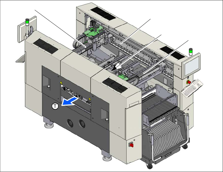
3.6.1 Gantry positions
3
Fig. 3.6 - 1 Position of gantries in the SX2 machines
(1) X axis, gantry 1
(2) Y axis, gantry 1 and gantry 2
(3) Y axis, gantry 1 and gantry 2 (concealed)
(4) X axis, gantry 2
(T) Direction of PCB transport
(1)
(2)
(4)
(3)
User manual SIPLACE SX1/SX2 3 Technical data and assemblies
From software version SC 706.1 SP1 Version 10/2014 3.6 Gantry system
125
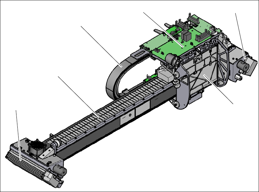
3.6.2 X axis structure
3
Fig. 3.6 - 2 Design of X axis - view of head mount
(1) Head mount with X axis linear motor (primary part)
(2) Y linear motor 2 with fixed bearing (primary part) and fan
(3) Guidance system with permanent magnet (secondary part of the X linear motor)
(4) Trailing cable
(5) Head board with Head Control Unit
(6) Y linear motor 1 with loose bearing (primary part) and fan
(4)
(3)
(1)
(5)
(2)
(6)
3 Technical data and assemblies User manual SIPLACE SX1/SX2
3.6 Gantry system From software version SC 706.1 SP1 Version 10/2014
126
3
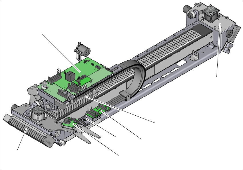
Fig. 3.6 - 3 Design of X axis - view of head mount
(1) Y linear motor 1 with loose bearing (primary part) and fan
(2) Head board with Head Control Unit
(3) Y linear motor 2 with loose bearing (primary part) and fan
(4) X axis linear motor (primary part)
(5) Gantry interface X axis
(6) Gantry interface Y axis
(7) Sensor module
(2)
(1)
(3)
(4)
(5)
(7)
(6)