00196962-04-BA-SX12-V2-EN.pdf - 第141页
User manual SIPLACE SX1/SX2 3 Technical data and assemblies From software version SC 706.1 SP 1 Version 10/2014 3.8 Vision system 141 3.8.4 PCB camera, type 34, digit al 3.8.4.1 Structure 3 Fig. 3.8 - 3 PCB camera, type …
3 Technical data and assemblies User manual SIPLACE SX1/SX2
3.8 Vision system From software version SC 706.1 SP1 Version 10/2014
140
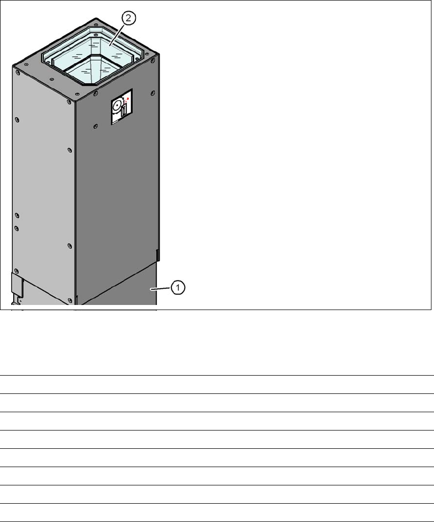
3.8.3 Component camera, stationary P&P, type 33, 55 x 45, digital
Item no. 119818-xx Stationary camera, type 33
3.8.3.1 Structure
3
Fig. 3.8 - 2 Structure for the stationary P&P component camera, type 33, 55 x 45, digital
3.8.3.2 Technical data
3
3
(1) Camera housing with integral camera
and camera amplifier
(2) Glass plate - illumination and lens levels
below
Component dimensions 1.0 mm x 0.5 mm to 55 mm x 45 mm
Component range 0402, MELF, SO, PLCC, QFP, electrolytic capacitors, BGA
Min. lead pitch 0.3 mm
Min. lead width 0.15 mm
Min. ball pitch 0.35 mm
Min. ball diameter 0.2 mm
Field of vision 65 mm x 50 mm
Illumination type Front-illumination (6 levels, programmable as required)
User manual SIPLACE SX1/SX2 3 Technical data and assemblies
From software version SC 706.1 SP1 Version 10/2014 3.8 Vision system
141
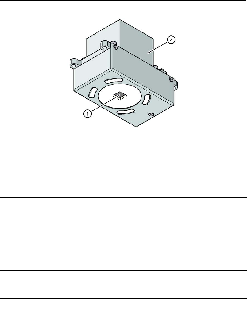
3.8.4 PCB camera, type 34, digital
3.8.4.1 Structure
3
Fig. 3.8 - 3 PCB camera, type 34, digital
(1) PCB camera lens and illumination
(2) Camera amplifier
3.8.4.2 Technical data
3
PCB fiducials Up to 3 (subpanels and multiple panels)
Up to 6 for the Long board option (Optional PCB fiducials are
output by the optimization).
Local fiducials Up to 2 per PCB (may be of different type)
Library memory Up to 255 fiducial types per subpanel
Image analysis Edge detection method (Singular feature) based on grayscale
values
Illumination type Front-illumination (3 levels, programmable as required)
Detection time per
fiducial/bad fiducial
20 ms - 200 ms
Field of vision 5.78 mm x 5.78 mm
Distance from the focus plane 28 mm

3 Technical data and assemblies User manual SIPLACE SX1/SX2
3.8 Vision system From software version SC 706.1 SP1 Version 10/2014
142
3.8.4.3 Fiducial criteria
3
3.8.4.4 Ink spot criteria
3
Locate 2 fiducials
Locate 3 fiducials
X-/Y-position, rotation angle, mean PCB distortion
additional: shearing, distortion separately in X and Y direction
Fiducial shapes Synthetic fiducials: circle, cross, square, rectangle, diamond,
circular, square and rectangular contours, double cross
Pattern: any
Fiducial surface
Copper
Tin
Without oxidation and solder resist
Warp ≤ 1/10 of structure width, both with good contrast to
environment
Dimensions of synthetic fiducials
Min. X/Y size for circle and rectangle:
Min. X/Y size for annulus and rectangle:
Min. X/Y size for cross:
Min. X/Y size for double-cross:
Min. X/Y size for rhombus:
Min. frame width for annulus and rectangle:
Min. bar width / bar distance for cross, double-cross:
Max. X/Y size for all fiducial shapes:
Max. bar width for cross, double-cross:
Min. tolerances, general:
Max. tolerances, general:
0.25 mm
0.3 mm
0.3 mm
0.5 mm
0.35 mm
0.1 mm
0.1 mm
3 mm
1.5 mm
2% of nominal dimension
20% of nominal dimension
Dimensions of patterns
Min. size
Max. size
0.5 mm
3 mm
Fiducial environment Clearance around reference fiducial not necessary if there is no
similar fiducial structure in the search area.
Methods - Synthetic fiducial recognition method
- Mean grayscale value
- Histogram method
- Template matching
Shapes and sizes of fiducials/
structures for
Synthetic fiducials
Other methods
For dimensions of synthetic fiducials, see Section Fiducial crite-
ria 3.8.4.3, page 142.
Min. 0.3 mm
Max. 5 mm
Masking material Good coverage
Recognition time Depends on the method: 20 ms - 0.2s