00196962-04-BA-SX12-V2-EN.pdf - 第256页
5 Working with the machine User manual SIPLACE SX1/SX2 5.9 Carrying out a sight check From software version SC 706.1 SP1 Version 10/2014 256 5.9.3 Checking the support pins Check the position of the support pins on the…

User manual SIPLACE SX1/SX2 5 Working with the machine
From software version SC 706.1 SP1 Version 10/2014 5.9 Carrying out a sight check
255
5
Check the multicolor status display (item 3 in fig. 5.9 - 1, page 254).
– If it lights up green, the feeder module is on standby.
– If it lights up orange, it is signaling a warning. The text of the warning
appears on the LCD display (item 4 in fig. 5.9 - 1
, page 254). The LEDs shine accordingly
for Smart Feeders.
– If the status display lights up red, a malfunction has occurred. The error message
appears on the LCD display (item 3 in fig. 5.9 - 1
, page 254). The LEDs shine accordingly
for Smart Feeders.
A list of the LCD and status displays on the operator panel is given in section 5.11
, page
270
. 5
A list of the LED and status displays on the Smart Feeder operator panel is given in sec-
tion 5.11.2
, page 271. 5
5
If the status display is off, the cause may be as follows: 5
– The feeder module is not in the current setup.
– The feeder module is defective.
– The feeder module has been disabled (due to a drop in pressure, for example)
5.9.2 Splicing the tapes in good time
5
5
CAUTION
Problems with cover foil withdrawal!
If the cover foil tears, this could lead to problems with the cover foil withdrawal.
There is an integral blade (item 2) for easily cutting the on the 8 and 12 mm X tape feeder
modules.
PLEASE NOTE
Late splicing of tapes
Late splicing of tapes can lead to prolonged down times.
Splice the tapes early enough so that the feeder modules do not run out of compo-
nents.
PLEASE NOTE
Early splicing of tapes
Early splicing of tapes can have the following consequence: when the old tape is rolled up
onto the new reel, the new reel could become too full and the tape will slide off it and get
caught up. This will again result in pick-up errors and prolonged down times.
Splice the tapes at the right time so that the old and new tapes do not get caught.
5 Working with the machine User manual SIPLACE SX1/SX2
5.9 Carrying out a sight check From software version SC 706.1 SP1 Version 10/2014
256
5.9.3 Checking the support pins
Check the position of the support pins on the lifting table:
– Make sure that the support pins do not collide with components on the underside of the
PCBs.
– In addition, make sure that the support pins do not collide with the PCB conveyor panels.
– To ensure safe and automatic positioning of the support pins, we recommend that you
use the Smart Pin Support option. See also section 6.15
, page 346.
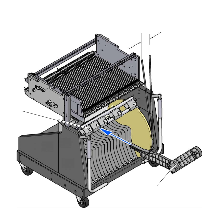
5.9.4 Mount of additional tape reel
5
Fig. 5.9 - 2 Mount of additional tape reel
(1) Mount of additional tape reel, item no. 00141217-xx
(2) Mounting device for the support
5
Max. 60 mm
(1)
(2)

User manual SIPLACE SX1/SX2 5 Working with the machine
From software version SC 706.1 SP1 Version 10/2014 5.9 Carrying out a sight check
257
X-Series feeder modules can process component tapes without problems if the lateral offset be-
tween the feeder module and the tape reel does not exceed 60 mm. If a predefined setup means
that the maximum permitted offset cannot be maintained, we recommend that you use the mount
for an additional tape reel (item 1). Simply insert the mount into the holder (item 2) and push it until
the offset is less than the maximum permitted value of 60 mm. The component trolley has 5 hold-
ers in total. Each tape reel mount can hold 2 tape reels, which means that up to ten 15" (381 mm)
tape reels can be positioned above the tape container.
5.9.5 Inserting separating plates into the tape container
The separating plate has different edges and can be inserted into the tape container in two
ways. If spindles are used, the recesses for the spindles in the separating plate point upwards
(see item 4 in fig. 5.9 - 3
). If you do not use spindles, the rounded edge of the separating
plate points up (see item 5 in fig. 5.9 - 3
).
Insert the separating plates as shown in fig. 5.9 - 3 and remember that the smallest division
of the tape container is a 2x division. This will help avoid placement errors.
Check that the separating plates engage in the same positions on the three guide rails. Oth-
erwise the separating plate will be offset or bent.