00191913-01.pdf - 第211页
User Manual SIPLACE 80S-20/F4 6 Vision functions Software version SR.406.xx 02/2000 Issue US 6.1 The vision systems on the placement machine 209 The PCB ca mera sy stem (see item 1 and 2 i n Fig. 6.1 - 5) essent ially c …
6 Vision functions User Manual SIPLACE 80S-20/F4
6.1 The vision systems on the placement machine Software version SR.406.xx 02/2000 Issue US
208
The fine pitch vision module is fixed to the machine base on the right of the PCB conveyor. 6
The component camera system can be used to optically center and place components up to and
including 55mm x 55mm in size. The minimum lead pitch can be as little as 0.4mm. A flip-chip
vision module can be fitted in addition to the fine pitch vision module as an option, in order to op-
tically center components up to 20mm x 20mm in size. The minimum lead pitch can be as little as
0.25mm. 6
6.1.3 PCB camera system
6
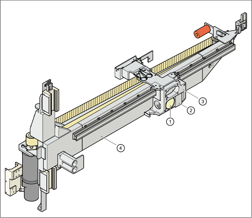
Fig. 6.1 - 5 PCB camera system, basic gantry – bottom view
(1) PCB camera – lens and illumination
(2) Camera amplifier
(3) Head mount
(4) Gantry
6
User Manual SIPLACE 80S-20/F4 6 Vision functions
Software version SR.406.xx 02/2000 Issue US 6.1 The vision systems on the placement machine
209
The PCB camera system (see item 1 and 2 in Fig. 6.1 - 5) essentially consists of the following
components: 6
– Optical lens
– CCD chip
– CCD camera amplifier
– An illumination level for illuminating PCB fiducials and ink spots
The PCB camera system is fixed to the revolver head on the underside of the gantry. As standard,
it can center PCBs from 50mm x 50mm up to 460mm x 460mm (2" x 2" to 18" x 18"), with the
thickness ranging from 0.5mm to 4.5mm. 6

6 Vision functions User Manual SIPLACE 80S-20/F4
6.1 The vision systems on the placement machine Software version SR.406.xx 02/2000 Issue US
210
6.1.4 Vision evaluation unit
The vision evaluation unit (see item 1 and 2 in Fig. 6.1 - 6) plugs into the machine’s control unit.
It processes and analyzes the electrical signals from the component and PCB camera systems.
Corrected values are calculated from any deviations from setpoint. These values are then used to
recalculate the placement positions and rotational angle for placement. 6
The vision evaluation unit also performs a component identification process. If the synthetic model
and the package form measurement do not tally, for example, the component will not be placed. 6
The precise component pick-up position, which is particularly important for small components, is
also determined in the vision evaluation unit. Fiducials on the feeders are used to determine the
deviation in position of the individual feeders. 6
The electronic image signals from components, PCB fiducials, and feeder fiducials can be trans-
ferred from the vision evaluation unit, via the video multiplexer, to the station monitor, where they
are used for measuring and testing purposes. 6
6
6
6
Key to Fig. 6.1 - 6
(1) MVS 340 vision evaluation unit
(2) COM1 interface
(3) COM2 interface
(4) HS
3
L interface
(5) Camera connections:
(6) Camera connections
6
6
S-20 F4
1 PCB camera, gantry 1 PCB camera
3 CO camera, gantry 1 CO camera, 12-segment revolver head
S-20 F4
2 PCB camera, gantry 2 Fine-Pitch-vision modul
4 CO camera, gantry 2 Flip-Chip-vision modul