00191913-01.pdf - 第460页
11 Station extensions / hardware User Manual SIPLACE 80S- 20/F4 11.1 Nozzle changer for the 12-segment revolver head Software version SR.406.xx 02/2000 Issue US 458 1 1.1.5 Position recognition Every magazine has a posit…

User Manual SIPLACE 80S-20/F4 11 Station extensions / hardware
Software version SR.406.xx 02/2000 Issue US 11.1 Nozzle changer for the 12-segment revolver head
457
11.1.4 Notes on operation
Å When you fill a magazine with a certain nozzle type for the first time, mark the magazine with
an adhesive label.
PLEASE NOTE 11
Only one nozzle type must be used in each magazine.
Fill the magazines off the machine, and always replace complete magazines. 11
Å Open the locking plate, and insert the nozzles into the nozzle holders.
Å Close the locking plate so that the nozzles cannot drop out of the magazines.
CAUTION 11
The magazines must not be filled until all the nozzles on the revolver head have been re-
turned to their magazines. 11
Å See the UNIX line computer user manual for instructions on programming the nozzle changer
on the line computer.
PLEASE NOTE 11
Å Be careful not to drop components onto the magazines, since they could cause the locking
plate to jam.
Å Also avoid dropping components onto free feeder locations, since the components will stick to
the magnetic bar. The work flow may be interrupted if the feeders are not placed on the com-
ponent feeder table correctly. You should therefore regularly clean the magazines and free
locations.
11 Station extensions / hardware User Manual SIPLACE 80S-20/F4
11.1 Nozzle changer for the 12-segment revolver head Software version SR.406.xx 02/2000 Issue US
458
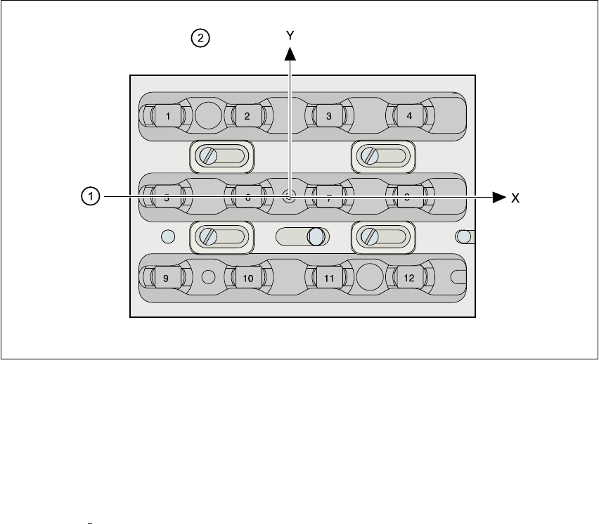
11.1.5 Position recognition
Every magazine has a position fiducial for position recognition purposes. 11
11
Fig. 11.1 - 3 Nozzle changer - position recognition
11
(1) Position fiducial
(2) Nozzle position in the magazine with respect to the position fiducial
11
See chapter 6
Vision functions for information on fiducial handling. 11
User Manual SIPLACE 80S-20/F4 11 Station extensions / hardware
Software version SR.406.xx 02/2000 Issue US 11.2 Component barcode
459
11.2 Component barcode
11.2.1 General
The placement machine allows the track assignment to be checked using a barcode reader, and
the component data to be read from the component reels. 11
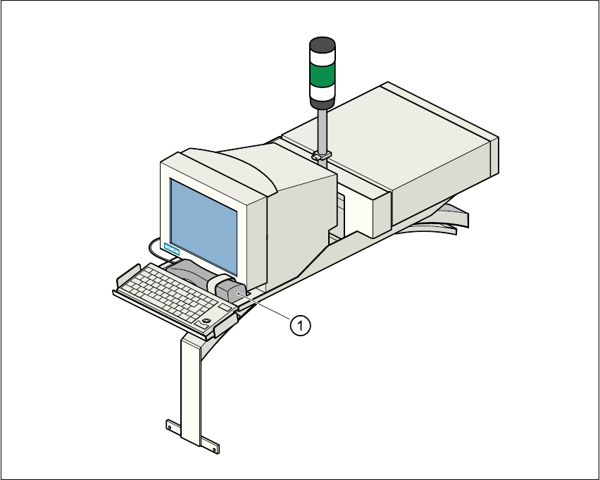
Fig. 11.2 - 1 Component barcode reader
(1) Barcode reader
Track allocation 11
There are four-digit barcode strips on the lateral protective covers in order to identify the track al-
location. The first digit is used to identify the component feeder table (1 or 2). The other three digits
indicate the track number. Return barcodes are provided at both ends of the barcode strip. The
barcode strips are numbered consecutively in intervals of two (1, 3, 5, 7, …), and each strip is used
for 2 tracks (barcode 1 = track 1 and 2). 11