00191913-01.pdf - 第511页
User Manual SIPLACE 80S-20/F4 11 Station extensions / hardware Software version SR.406.xx 02/2000 Issue US 11.9 Flux dispenser unit 509 Rinse fluxer head: 11 The fluxer h ead ca n be rins ed to rem ove flux residues or a…
11 Station extensions / hardware User Manual SIPLACE 80S-20/F4
11.9 Flux dispenser unit Software version SR.406.xx 02/2000 Issue US
508
11
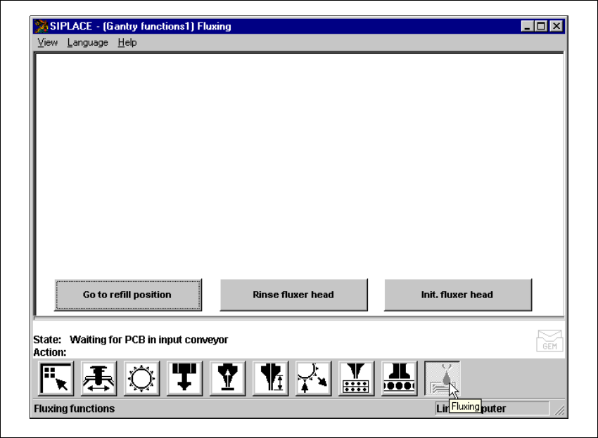
Fig. 11.9 - 12 Gantry functions
(1) Buttons for the fluxing single functions (flux)
Go to refill position: 11
To change the syringe, you must first move the syringe piston to its bottom position, and move the
machine into a suitable position (refill position). 11
Å Click on the Go to refill position button. The fluxer head will move to the refill position, and
the syringe piston will move down. The syringe can then be changed. See Section 11.9.5
Changing the syringe.
The fluxer head must be moved to the refill position before any work is carried out on it. The flux
must be refilled in this position. 11
Å Click on the Go to refill position button, and press the Start button. The fluxer head will move
to the refill position.
User Manual SIPLACE 80S-20/F4 11 Station extensions / hardware
Software version SR.406.xx 02/2000 Issue US 11.9 Flux dispenser unit
509
Rinse fluxer head: 11
The fluxer head can be rinsed to remove flux residues or air bubbles from the dispensing hose,
for example. This will prevent the dispensing hose and centering nozzle from hardening, or air
bubbles causing fluxing errors. 11
Å Click on the Rinse fluxer head button, and press the Start button. The fluxer head will move
over the rinsing tank, and dispense the syringe contents into the rinsing tank.
The rinsing tank is beside the component reject bin (see Fig. 11.9 - 10).
Initialize fluxer head: 11
It is possible to carry out a fluxer head reference run. 11
Å Click on the Init. fluxer head button, and press the Start button. The fluxer head will carry out
a reference run.
11 Station extensions / hardware User Manual SIPLACE 80S-20/F4
11.10 PCB data transfer Software version SR.406.xx 02/2000 Issue US
510
11.10 PCB data transfer
11.10.1 Functional description
The ‘PCB data transfer’ option has been included in the ‘Machine options’ menu. The aim of this
function is to increase the line performance of your placement system by fully measuring a PCB
at the
first
placement machine, determining the associated fiducial, subpanel, ink spot, etc, data,
saving this data and then sending it to the next machine. At the next machine, it is then only nec-
essary to determine the data for two fiducial positions. These two fiducial positions are then used
to correct the position of each subsequent machine for the PCB to be placed. It is thus not neces-
sary to measure the entire PCB, together with its subpanels, ink dots, etc. 11
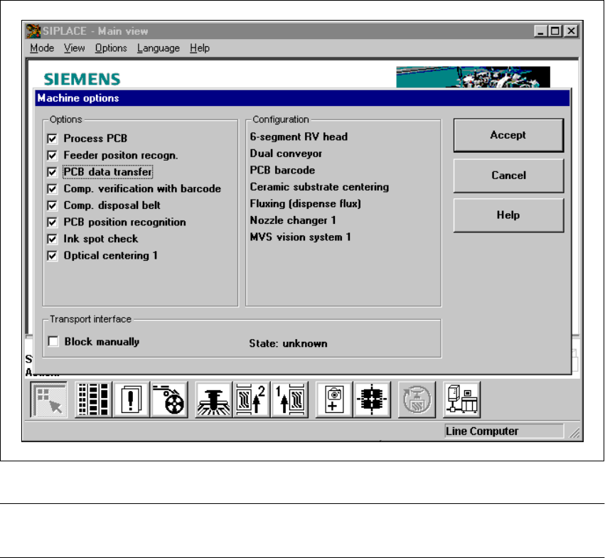
Fig. 11.10 - 1 Machine option: PCB data transfer
PLEASE NOTE: The PCB data transfer function can only be used if a PCB barcode reader is in-
stalled. 11