00191913-01.pdf - 第367页
User Manual SIPLACE 80S-20/F4 7 What should you do ... Software version SR.406.xx 02/2000 Issue US 7.3 Changing jobs 365 7.3 Changing j obs Å Interr upt the job define d for the stat ion on the lin e comput er using t he…
7 What should you do ... User Manual SIPLACE 80S-20/F4
7.2 Switching off the SIPLACE line Software version SR.406.xx 02/2000 Issue US
364
7.2.3 Starting stations that remain switched on after the line computer has been
shut down
If stations remain switched on after the line computer has been shut down and the line computer
is then restarted, the computer will not automatically establish connections with those stations.
The following error messages may appear on the line computer monitor: 7
– No correct connection between line computer and station
– The line computer was shut down and restarted, so the station must also be shut down and
restarted.
7
There are two ways of re-establishing the connection between the line computer and station after
the line computer has been shut down: 7
1st option 7
Å Disable the conveyor interface at the stations from the ‘Machine options’ menu.
Å Run all the PCB feeders on the line until they are empty.
Å Switch the stations off and on again.
The stations will establish connections with the line computer.
Å Press the Start button when prompted. The reference point run will then be carried out.
Å Continue placement.
2nd option 7
Å Select the ‘Line engineer’ access level (password required) from the ‘Options’ menu.
Å Select the ‘Stand-alone’ option from the ‘Operating mode’ menu.
The PCB conveyor for the station will run on until empty.
Å Wait until you are prompted to press the Start button.
Å Select ‘Line computer’ from the ‘Operating mode’ option in the ‘Options’ menu.
The station will automatically establish a connection with the line computer.
Å Press the Start button.
The reference point run will then be carried out.
Å Set the access level back to ‘Operator’.
Å Continue placement.
User Manual SIPLACE 80S-20/F4 7 What should you do ...
Software version SR.406.xx 02/2000 Issue US 7.3 Changing jobs
365
7.3 Changing jobs
Å Interrupt the job defined for the station on the line computer using the function (Interrupt).
Å Enter the new job on the line computer using the function (Schedule).
Å Check the width of the conveyor belt.
Å Check the position of the magnetic supports and make sure that they cannot collide with com-
ponents on the bottom of the PCB.
Å Carry out the set-up check.
Make sure that the feeder modules are equipped with the correct components and that the
feeder modules are at the correct locations.
Å Check the nozzle configuration in the nozzle changer.
If no nozzle changer is installed, then you must change the nozzles manually.
NOTE
If you change the nozzle manually, ALWAYS make sure that you are using the correct nozzle
type and that the nozzle is seated correctly on the spindle. (The plunger pin must click into
place in the notch slot of the nozzle).
If you have not inserted a nozzle or have used the wrong nozzle type, then the station com-
puter program will prompt you to move the placement head to the service position and change
the nozzle. This error message will also appear if you have not inserted the nozzle correctly.
If you insert the wrong nozzle or use the wrong nozzle type again, then the gantry will move to
the service position once more after the reference sequence. The station computer program
will continue to prompt for a nozzle change until you have obtained the correct configuration. If
you do not succeed, then proceed as follows:
Å Switch off the station and cancel the specified job on the line computer.
Å Rectify the nozzle error and restart the station.
7 What should you do ... User Manual SIPLACE 80S-20/F4
7.3 Changing jobs Software version SR.406.xx 02/2000 Issue US
366
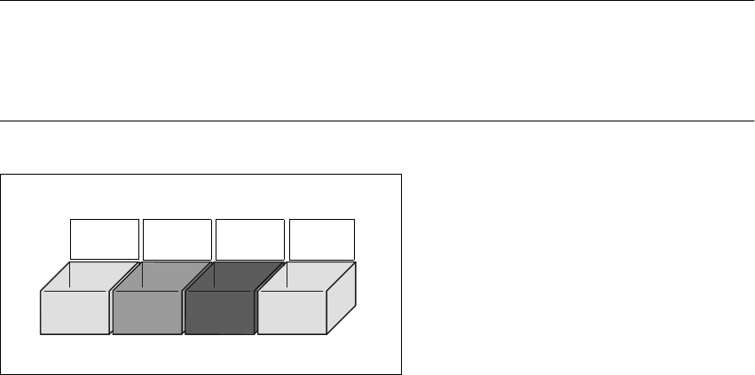
TIP
Have the nozzles ready in a separate nozzle box in which each compartment is labeled with the
type and color of the nozzle. This will help to prevent confusion. Do not save used plastic nozzles,
dispose of them immediately instead. 7
7
Fig. 7.3 - 1 Example of a nozzle box
7
701
yellow
704
orange
705
red
711
yellow