00191913-01.pdf - 第493页
User Manual SIPLACE 80S-20/F4 11 Station extensions / hardware Software version SR.406.xx 02/2000 Issue US 11.8 Coplanarit y laser module (80F4) 491 1 1.8.5 Dat a entry – Enter the coplan arity me asureme nt under ‘Ha nd…
11 Station extensions / hardware User Manual SIPLACE 80S-20/F4
11.8 Coplanarity laser module (80F4) Software version SR.406.xx 02/2000 Issue US
490
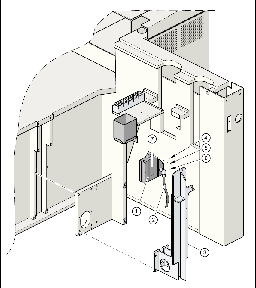
Fig. 11.8 - 5 Coplanarity laser module
(1) Laser module
(2) Connecting cable
(3) Supporting frame
(4) Red LED: OUT OF RANGE
(5) Red LED: POOR TARGET
(6) Green LED: LASER ON
(7) Class 3 B Laser Product, see Fig. 11.8 - 2

User Manual SIPLACE 80S-20/F4 11 Station extensions / hardware
Software version SR.406.xx 02/2000 Issue US 11.8 Coplanarity laser module (80F4)
491
11.8.5 Data entry
– Enter the coplanarity measurement under ‘Handling data’ in the package form editor (see sec-
tion 5.4.4 of the SIPLACE UNIX line computer user manual).
– Enter the maximum deviation from coplanarity (see max. component height tolerance, section
5.2.5 ‘NU editor functions’ of the SIPLACE UNIX line computer user manual).
PLEASE NOTE
You can activate or deactivate the coplanarity laser module from the ‘"Options" menu’ (see section
3.3.2.3 of this user manual). The coplanarity measurement can be switched off or on for those
components for which the coplanarity measurement is set in the package form data. 11

11 Station extensions / hardware User Manual SIPLACE 80S-20/F4
11.9 Flux dispenser unit Software version SR.406.xx 02/2000 Issue US
492
11.9 Flux dispenser unit
11.9.1 Overview
Reliable processing of flip-chip components requires a flux to be applied before the component is
placed. This ensures that the subsequent soldering process will be successful. 11
Once the Pick&Place head has picked up the flip-chip component, and a position measurement
has been carried out, the flux is dispensed at the placement position on the PCB. The volume of
flux to be dispensed can be entered for specific package forms. 11
The Pick&Place head inserts the flip-chip component as soon as the flux has been dispensed.
The Pick&Place head hold the flip-chip component in position on the PCB for a programmable,
package form-specific time. This causes the component to dry onto the flux, thus preventing it
from “floating away”. 11
Once all the flip-chip components have been placed, the PCB conveyor is activated after a pro-
grammable waiting time in order to remove the PCB. 11
11.9.2 Technical data
11
Dispensing volume 2 µl - 100 µl
Smallest dosing increment 1 µl
Syringe volume 1 ml
Tank volume 100 ml
Volume to be dispensed at the mounting location Depends on the flip-chip size, and the wetting prop-
erties of both flux and substrate material.
Flip-chip holding time after placement 0 to 5 sec
Holding time increment 0.01 sec
Minimum waiting time before PCB is transported 0 to 40 sec
Waiting time increment 1 sec
Dispensing cycle time 1.5 sec, including positioning
Rinse cycle 1 to 10 x syringe content
Filling level 1 Warning
Filling level 2 Empty, i.e. machine stopped
Positioning accuracy of the dispensing needle ± 0.05 mm