00191913-01.pdf - 第38页
1 Introduction User Manual SIPLACE 80S-20/F4 1.5 Description of the machine S oftware version SR.406.xx 02/2000 I ssue US 36 1.5.5 T echnica l dat a – overview of t he SIPL ACE 80F 4 Procedu re Collect & place Compon…
User Manual SIPLACE 80S-20/F4 1 Introduction
Software version SR.406.xx 02/2000 Issue US 1.5 Description of the machine
35
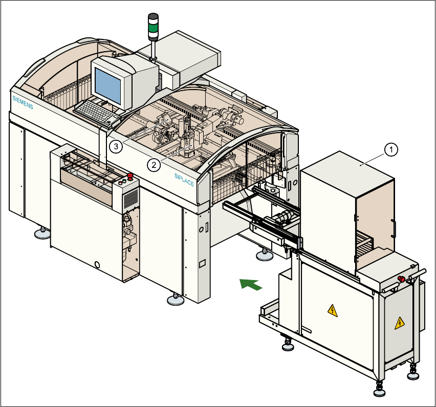
1.5.4 General view of the SIPLACE F
4
with wafflepack changer
1
Fig. 1.5 - 3 General view of the F
4
with wafflepack changer
(1) Wafflepack changer
(2) Pick&Place head
(3) 12-segment revolver head

1 Introduction User Manual SIPLACE 80S-20/F4
1.5 Description of the machine Software version SR.406.xx 02/2000 Issue US
36
1.5.5 Technical data – overview of the SIPLACE 80F
4
Procedure Collect&place
Component range
Standard vision module from 0402 to 55mm x 55mm
Max. placement rate
12-segment revolver head
Pick&Place head
10,000 components/hour
1,800 components/hour
12-segment revolver head
Angular accuracy
Placement accuracy
± 0.525°/ 3 σ, ± 0.70°/ 4 σ, ± 1.05°/ 6 σ
± 67.5µm / 3 σ, 90µm / 4 σ, 135µm / 6 σ
± 45µm / 3 σ, 60µm / 4 σ, 90µm / 6 σ) **
Pick&Place head
Angular accuracy
Placement accuracy
± 0.052°/ 3 σ, ± 0.07°/ 4 σ, ± 0.105°/ 6 σ
± 37.5µm / 3 σ, 50µm / 4 σ, 75µm / 6 σ
PCB format 50mm x 50mm to 460mm x 460mm
(optionally 460mm x 508mm, 18" x 20")
Feeder capacity 40 locations for feeders
Component supply
Types of feeder
Changeover table, wafflepack changer, manual WPC
trays, component tapes, stick magazines, bulk cases
Operating system Microsoft Windows NT / RMOS
Connection In-line or stand alone
Space required 4 m² / module

User Manual SIPLACE 80S-20/F4 1 Introduction
Software version SR.406.xx 02/2000 Issue US 1.6 The line concept
37
1.6 The line concept
1.6.1 Overview
The machine can be linked to input/output stations, screen printing systems, soldering ovens and
other machines from the SIPLACE range (HS-50, S-20, F
4
, F
5
/F
5
HM, and the SIPLACE G adhe-
sive application station). All SIPLACE modules are supplied with the necessary data by the UNIX
line computer. The placement machine can also be linked to a higher level data processing system
through the use of suitable interfaces. 1
1.6.2 Technical data – line concept
1
*) SIPLACE HS-50, SIPLACE 80 S-20, SIPLACE 80 S-23 HM or SIPLACE 80 F
4
with 12-segment
revolver head 1
**) SIPLACE 80 F
4
/F
5
/F
5
HM 1
1
1
System SIPLACE placement lines
Modules SIPLACE HS-50 / SIPLACE 80 S-20 / SIPLACE S-23 HM
SIPLACE 80 F
4
/ SIPLACE F
5
/ SIPLACE F
5
HM
Peripherals Input/output stations
Screen printers
Soldering ovens
Inspection stations, etc.
Component range From 0402 * to 55 mm x 55 mm **
PCB conveyor Automatic width adjustment
PCB format 50 mm x 50 mm to 460 mm x 460 mm
Placement rate Depends on how the modules are connected to one another
Space required 4 m² / SIPLACE 80 module
7.5 m² / SIPLACE HS-50 module