00191913-01.pdf - 第37页
User Manual SIPLACE 80S-20/F4 1 Introduction Software vers ion SR.406.xx 0 2/2000 Issue US 1.5 D escription of the machine 35 1.5. 4 Gener al vie w of the S IPLAC E F 4 with wafflep ack changer 1 Fig. 1.5 - 3 General vie…
1 Introduction User Manual SIPLACE 80S-20/F4
1.5 Description of the machine Software version SR.406.xx 02/2000 Issue US
34
The F
4
placement machine is a high-speed placement machine with a gantry axis system. The
gantry supports: 1
– a PCB vision module,
– a star-shaped 12-segment revolver head, and
– a Pick&Place head.
The 12-segment revolver head will increase the placement rate if the proportion of ICs in the
placement process is very high. 1
The Pick&Place head is particularly suitable for inserting fine pitch components. In addition to the
vision module for PCB centering, the F
4
machine also has component vision modules for the re-
volver head and Pick&Place head. 1
A coplanarity laser module and a flip chip vision module can also be retrofitted as options. 1
A wafflepack changer can be used to supply components. 1
The placement heads pick up components from stationary feeders and then place them in the
PCBs clamped on the PCB conveyor. 1
1
The concept behind the placement machine 1
– with its stationary feeders,
– with PCBs that do not move during placement,
– and its positionable placement heads
has number of significant benefits: 1
– For example, the flexible 12-segment revolver head combined with automatic nozzle changer
enables the nozzle configuration to be changed temporarily and automatically adapted to re-
ceive different component sizes You can also optimize the travel paths, and the placement se-
quence.
– With stationary feeders, even the tiniest components are picked up reliably.
– The components cannot slip on the PCB during placement (as is often the case with moving
PCBs) since the PCB does not move.
– Sophisticated optical centering systems (vision systems) for components and PCBs also en-
sure high component positioning accuracy.
– Components can be topped up and tapes can be spliced without stopping the machine.
– Prepared component tables enable the placement machine to be retooled without long idle
times.
1
User Manual SIPLACE 80S-20/F4 1 Introduction
Software version SR.406.xx 02/2000 Issue US 1.5 Description of the machine
35
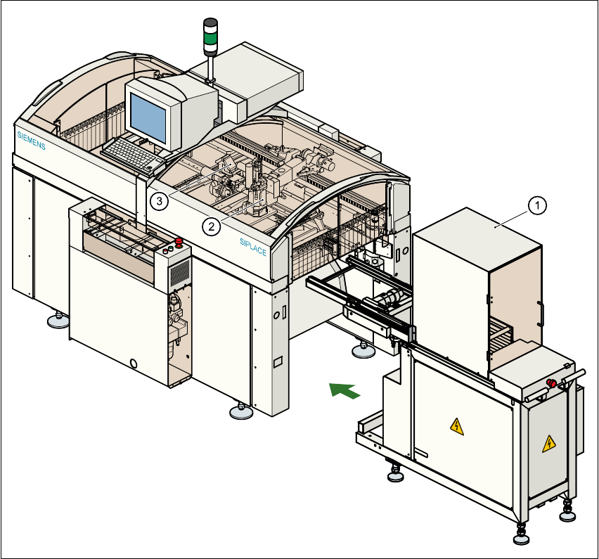
1.5.4 General view of the SIPLACE F
4
with wafflepack changer
1
Fig. 1.5 - 3 General view of the F
4
with wafflepack changer
(1) Wafflepack changer
(2) Pick&Place head
(3) 12-segment revolver head

1 Introduction User Manual SIPLACE 80S-20/F4
1.5 Description of the machine Software version SR.406.xx 02/2000 Issue US
36
1.5.5 Technical data – overview of the SIPLACE 80F
4
Procedure Collect&place
Component range
Standard vision module from 0402 to 55mm x 55mm
Max. placement rate
12-segment revolver head
Pick&Place head
10,000 components/hour
1,800 components/hour
12-segment revolver head
Angular accuracy
Placement accuracy
± 0.525°/ 3 σ, ± 0.70°/ 4 σ, ± 1.05°/ 6 σ
± 67.5µm / 3 σ, 90µm / 4 σ, 135µm / 6 σ
± 45µm / 3 σ, 60µm / 4 σ, 90µm / 6 σ) **
Pick&Place head
Angular accuracy
Placement accuracy
± 0.052°/ 3 σ, ± 0.07°/ 4 σ, ± 0.105°/ 6 σ
± 37.5µm / 3 σ, 50µm / 4 σ, 75µm / 6 σ
PCB format 50mm x 50mm to 460mm x 460mm
(optionally 460mm x 508mm, 18" x 20")
Feeder capacity 40 locations for feeders
Component supply
Types of feeder
Changeover table, wafflepack changer, manual WPC
trays, component tapes, stick magazines, bulk cases
Operating system Microsoft Windows NT / RMOS
Connection In-line or stand alone
Space required 4 m² / module