00191913-01.pdf - 第500页
11 Station extensions / hardware User Manual SIPLACE 80S- 20/F4 11.9 Flux dispenser unit Software vers ion SR.406.xx 02/2000 I ssue US 498 CAUTION When you unscre w the cente ring noz zle, mak e sure that you do not lo s…
User Manual SIPLACE 80S-20/F4 11 Station extensions / hardware
Software version SR.406.xx 02/2000 Issue US 11.9 Flux dispenser unit
497
11.9.6 Replacing the complete dispensing needle and centering nozzle
If the centering nozzle is defective, it can be replaced on its own. The dispensing needle is a com-
plete module, however. It may be necessary to change the complete dispensing needle if it or the
hose becomes clogged due to crystallization of the flux. In this case, the complete module must
be replaced. 11
11
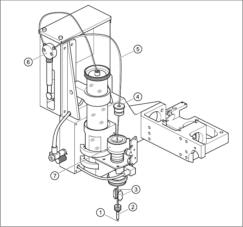
Fig. 11.9 - 4 Changing the dispensing hose (tube blunt 29")
(1) Tip of dispensing needle (2) Centering nozzle
(3) Clamping parts (4) Lid of cylinder
(5) Complete dispensing needle (6) Valve
(7) Cylinder 11

11 Station extensions / hardware User Manual SIPLACE 80S-20/F4
11.9 Flux dispenser unit Software version SR.406.xx 02/2000 Issue US
498
CAUTION
When you unscrew the centering nozzle, make sure that you do not lose the two clamping parts
that hold the dispensing needle in the cylinder. 11
Å Loosen the centering nozzle.
Å Pull the cylinder lid away from the cylinder, and pull the complete dispensing needle out of the
cylinder.
Å Disconnect the dispensing needle hose from the valve of the dispensing pump.
Å Thread the new dispensing needle through the cylinder lid, through the cylinder and into the
centering nozzle. The tip of the dispensing needle must protrude approximately 3 mm from the
centering nozzle.
Å Tighten the centering nozzle once more.
Å Press the lid onto the cylinder.
Å Check the distance between the dispensing needle and the PCB. Press the down on the piston
– the distance must now be approximately 1 mm.
If this is not the case, you will have to reset the distance.
User Manual SIPLACE 80S-20/F4 11 Station extensions / hardware
Software version SR.406.xx 02/2000 Issue US 11.9 Flux dispenser unit
499
11.9.6.1 Setting the distance between the dispensing needle and the PCB
11
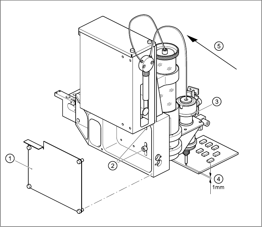
Fig. 11.9 - 5 Setting the distance between the dispensing needle and the PCB
11
Å Loosen the 4 fixing screws for the rear panel of the flux dispenser, and remove the panel.
Å Loosen the two fixing screws in the slots.
Å Press down on the lifting piston, and adjust the flux dispenser so that the distance between the
tip of the dispensing needle and the PCB is 1 mm.
(1) Rear panel with four fixing screws
(2) Two fixing screws for the flux dispenser
(3) Lifting piston
(4) Set a distance of 1 mm with respect to the PCB
(5) Press the flux dispenser right down against the stop