00191913-01.pdf - 第57页
User Manual SIPLACE 80S-20/F4 1 Introduction Software version SR.406.xx 02/2000 Issue US 1.13 Overview of the modules - placement heads 55 – The co mponent vision camer a crea tes an im age of th e curr ent co mponent . …
1 Introduction User Manual SIPLACE 80S-20/F4
1.13 Overview of the modules - placement heads Software version SR.406.xx 02/2000 Issue US
54
1.13 Overview of the modules - placement heads
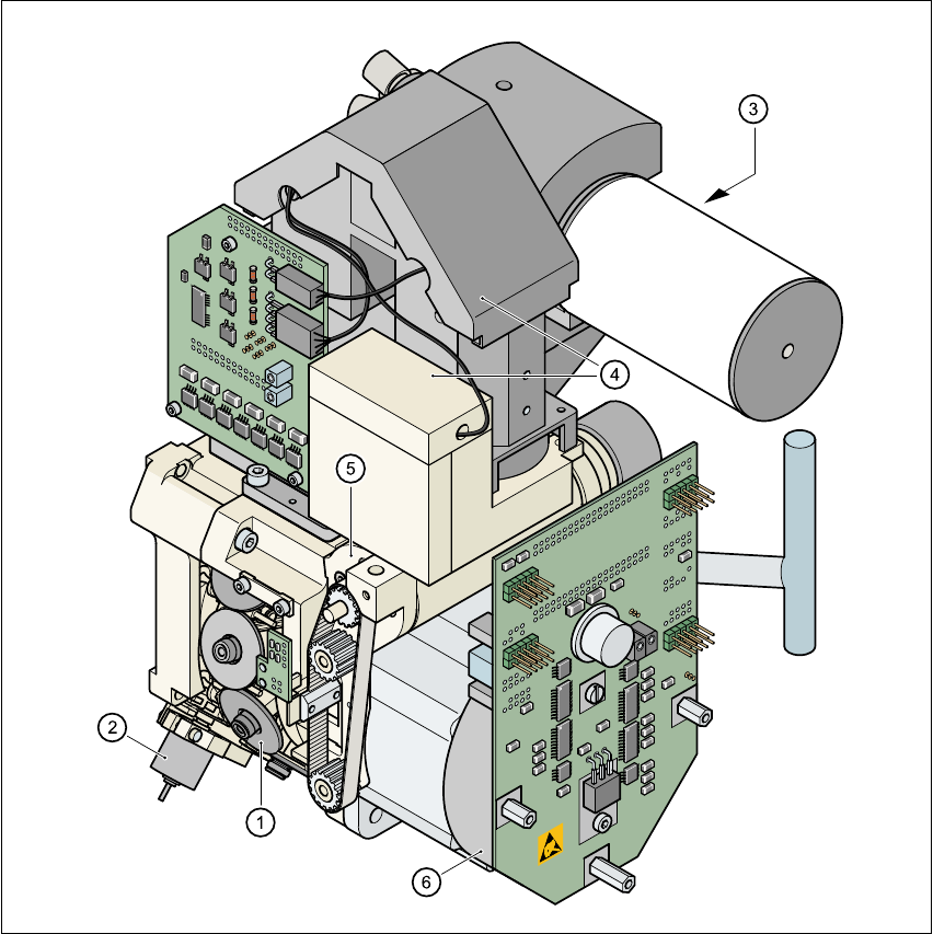
1.13.1 Structure of the 12-segment revolver head
1
Fig. 1.13 - 1 Structure of the 12-segment revolver head
All the components are inserted with the same cycle time. Before the component is inserted, it is
measured by the optoelectronic vision module. 1
(1) Star with 12 sleeves (2) Motor for "Reject" valve adjustment drive
(3) Turning station (4) Component vision module
(5) Z axis driving mechanism (6) Star motor

User Manual SIPLACE 80S-20/F4 1 Introduction
Software version SR.406.xx 02/2000 Issue US 1.13 Overview of the modules - placement heads
55
– The component vision camera creates an image of the current component.
– The precise position of the component is also determined.
– The package form of the current component is compared against the programmed package
form in order to identify it. Any components that cannot be identified are rejected.
– The turning station turns the component to the required placement angle.
1.13.2 Description of the 12-segment revolver head
– The 12-segment revolver head works using the "Collect & Place" principle, i.e. the components
are held by the nozzles with the aid of a vacuum and, after one complete pick-up cycle, are
placed gently and accurately on the PCB with the aid of blast air. The vacuum in the nozzles
is also checked several times to determine whether the components were picked up and set
down correctly.
– The "adaptive" sensor stop mode of the Z-axis compensates for any irregularity of the
PCB-surface when the components are set down.
– Defective components are rejected, and are reworked during a repair cycle.
1.13.3 Technical data of the 12-segment revolver head
Component range 0402 to 18.7mm x 18.7mm including BGA, µBGA,
flip chip, TSOP, QFP, PLCC, SO to SO32, DRAM
Max. height 6 mm
Min. lead pitch 0.5 mm
Min. dimensions 0.5 mm x 1.0 mm
Max. dimensions 18.7 mm x 18.7 mm
Max. weight 2 g
Max. travel of z axis 16 mm
Programmable placement force 2.4 to 5.0 N
Nozzle types 7xx
Angular accuracy ± 0.525° / 3 σ, ± 0.70° / 4 σ, ± 1.05° / 6 σ
Placement accuracy ± 67.5 µm / 3 σ, ± 90 µm / 4 σ, ± 135 µm / 6 σ
1 Introduction User Manual SIPLACE 80S-20/F4
1.13 Overview of the modules - placement heads Software version SR.406.xx 02/2000 Issue US
56
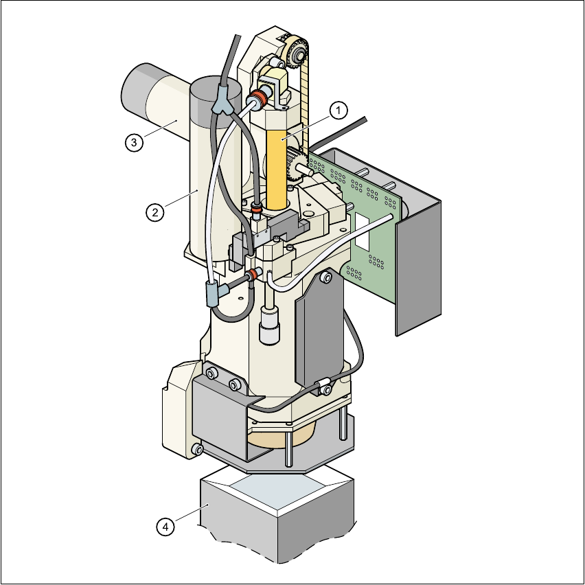
1.13.4 Structure of the Pick&Place head
1
Fig. 1.13 - 2 Structure of the Pick&Place head.
(1) Sleeve
(2) DR axis driving mechanism
(3) Z axis driving mechanism
(4) Fine pitch vision module