00191913-01.pdf - 第62页
1 Introduction User Manual SIPLACE 80S-20/F4 1.15 Overview of the modules - PCB conveyor Software version SR.406.xx 02/2000 Issue US 60 1.15 Overv iew of the modules - PCB conveyor 1.15.1 Structure of the PCB conveyor Th…

User Manual SIPLACE 80S-20/F4 1 Introduction
Software version SR.406.xx 02/2000 Issue US 1.14 Overview of the modules - vision systems
59
1.14.2 Technical data - fine pitch vision module
1.14.3 Technical data – PCB vision module
Max. component size
32mm x 32mm (single measurement)
55mm x 55mm (multiple measurement)
(larger components available upon request)
Component range
PLCC, LCCC, QFP, SO, BGA, flip chip,
components with leads up to 55mm x 55mm
(J-leads and gull wings, balls, bumps)
Minimum lead pitch 0.2 mm
Field of view 38mm x 38mm
Method of illumination Front lighting (3 levels programmable as required)
Fiducials Up to 3 per placement program
Local fiducials Up to 2 per component (may be of different types)
Library size Up to 255 types of fiducial – system fiducials ≥ 249
Image processing Gray scale value-based correlation principle
Method of illumination Front lighting
Fiducial recognition time per fiducial/ink spot 0.4 s
Field of view 5.7 mm x 5.7 mm
1 Introduction User Manual SIPLACE 80S-20/F4
1.15 Overview of the modules - PCB conveyor Software version SR.406.xx 02/2000 Issue US
60
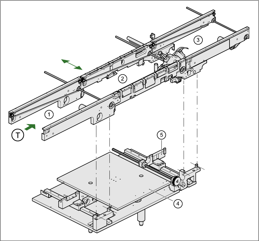
1.15 Overview of the modules - PCB conveyor
1.15.1 Structure of the PCB conveyor
The machine is supplied with a single conveyor as standard. The dual conveyor is available as an
option. The left or the right side of the PCB conveyor can be used as the stationary side, as re-
quired. 1
1
Fig. 1.15 - 1 PCB conveyor - single conveyor
(1) Input conveyor (2) Center conveyor
(3) Output conveyor (4) Lifting table
(5) Width adjustment T PCB transport direction 1

User Manual SIPLACE 80S-20/F4 1 Introduction
Software version SR.406.xx 02/2000 Issue US 1.15 Overview of the modules - PCB conveyor
61
The conveyor belts are driven by DC motors. The lifting table near the center conveyor clamps the
PCBs in position. The width of the PCB conveyor can be adjusted, either using the menu or from
the line computer. 1
1.15.2 Technical data – single conveyor
1
1.15.3 Technical data – dual conveyor
1
PCB format
50mm x 50mm to 460mm x 460mm
2" x 2" to 18" x 18"
Optionally:up to 508mm x 460mm
up to 20" x 18 "
PCB thickness 0.5mm to 4.5mm
Max. PCB warpage
On top: 4.5mm - PCB thickness
On bottom: 0.5mm + PCB thickness
Clearance on PCB underside 25mm (standard), 40mm (option)
PCB transport height
830mm ± 15mm (standard)
900mm ± 15mm (option)
930mm ± 15mm (option)
950mm ± 15mm (SMEMA: optional)
Fixed conveyor edge Right (standard), left (optional)
Type of interface Siemens (standard), (SMEMA: optional)
Component-free handling edge 3mm
PCB changeover time 2.5 s
PCB format
50mm x 50mm to 460mm x 216mm
2" x 2" to 18" x 8.5"
Optionally:up to 508mm x 216mm
up to 20" x 8.5 "
PCB thickness 0.5mm to 4.5mm
Max. PCB warpage
On top: 4.5mm - PCB thickness
On bottom: 0.5mm + PCB thickness
Clearance on PCB underside 25mm (standard), 40mm (option)