00191913-01.pdf - 第32页
1 Introduction User Manual SIPLACE 80S-20/F4 1.5 Description of the machine S oftware version SR.406.xx 02/2000 I ssue US 30 1.5 Description of the machine 1.5.1 SIPLACE 80S-20 functional description The S-20 au tomatic …

User Manual SIPLACE 80S-20/F4 1 Introduction
Software version SR.406.xx 02/2000 Issue US 1.4 Revision index
29
1.4.7 Overview of the revisions in the 02/00 issue
New or modified Chapter/Section
SIPLACE on the World Wide Web (WWW) 1.1.1
Safety instructions for the PCB barcode reader (option) 2.1.9
Safety instructions for coupling and uncoupling the mobile
changeover table
2.1.10
Safety instructions for changing the height of component tables 2.1.11
Safety instructions for the changeable component feeder table 2.1.12
"Mode" menu6WDUW6,3/$&( 2,6 3.3.2.1
"Mode" menu6WDUWSIPLACE Pro 3.3.2.1
"Mode" menu&RQILJXUHSIPLACE PRO connection 3.3.2.1
"Options" menu&RQWUROPRGH6,3/$&(3UR 3.3.2.3
"Options" menu, Cluster for fine calibration
3.3.2.3
Printing a help topic 9.1.2.2
Vision functions 6
What should you do ... 7
3 x 8 mm S module 10.2.2
Component disposal module (80F4) 10.2.10
PCB barcode 11.4
Coplanarity laser module (80F4) 11.8
Fine calibration 11.12
1 Introduction User Manual SIPLACE 80S-20/F4
1.5 Description of the machine Software version SR.406.xx 02/2000 Issue US
30
1.5 Description of the machine
1.5.1 SIPLACE 80S-20 functional description
The S-20 automatic placement system is a high-performance placement system with two gantry
axis systems. A PCB vision system and a star-shaped 12-segment revolver head are mounted on
each gantry. Revolver placement heads equipped with a component vision system pick up the
components from stationary feeder modules and place them onto the PCB clamped in the PCB
conveyor. 1
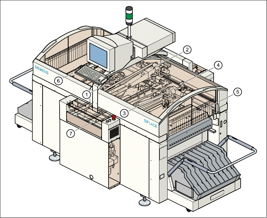
Fig. 1.5 - 1 Functional description of the 80S-20 placement system
(1) 12-segment revolver head with component vision module (gantry 1)
(2) Gantry 1 with PCB vision module
(3) 12-segment revolver head with component vision module (gantry 2)
(4) Gantry 2 with PCB vision module
(5) Stationary component supply (location 1)
(6) Stationary component supply (location 3)
(7) PCB conveyor (dual conveyor option)
User Manual SIPLACE 80S-20/F4 1 Introduction
Software version SR.406.xx 02/2000 Issue US 1.5 Description of the machine
31
The concept behind the automatic placement system 1
– with its stationary feeder modules,
– PCBs that do not move during placement
– and positionable placement heads
has a number of significant benefits: 1
– For example, the flexible 12-segment revolver heads combined with automatic nozzle chang-
ers enable the nozzle configuration to be changed temporarily and automatically adapted to
receive different component sizes.
– You can also optimize the traversing paths and the placement sequence.
– With stationary feeder modules, even the tiniest components are picked up reliably.
– The components cannot slip on the PCB during placement (as is often the case with moving
PCBs) since the PCB does not move.
– Sophisticated optical centering systems (vision systems) for components and PCBs also en-
sure high component positioning accuracy.
– Components can be topped up and tapes can be spliced without stopping the machine.
– Prepared component tables enable the placement system to be retooled without long stop-
pages.