SIPLACE Vision Customer_en.pdf - 第100页
Component Shapes Specific Component Shapes Optical Recognition of Free Programmed COs S tudent Guide SIPLACE V ision (Customer) Component Shapes Edition 12/2008 EN 100 Error processing If error messages are issued during…
Component Shapes
Optical Recognition of Free Programmed COs Specific Component Shapes
Student Guide SIPLACE Vision (Customer)
Edition 12/2008 EN Component Shapes
99
Joint datasets with ICOS data NOT possible –
Applicable if SIPLACE Vision uses one of its own special recognition procedures (e.g. for corners or
special lead shapes).
5.3.14 Optical Recognition of Free Programmed COs
The Nonstandard centering procedure determines the CO center position from the recognition steps
required for the individual lead. This involves both coarse and fine measurement. Component inspection
can also be enabled or disabled, as required.
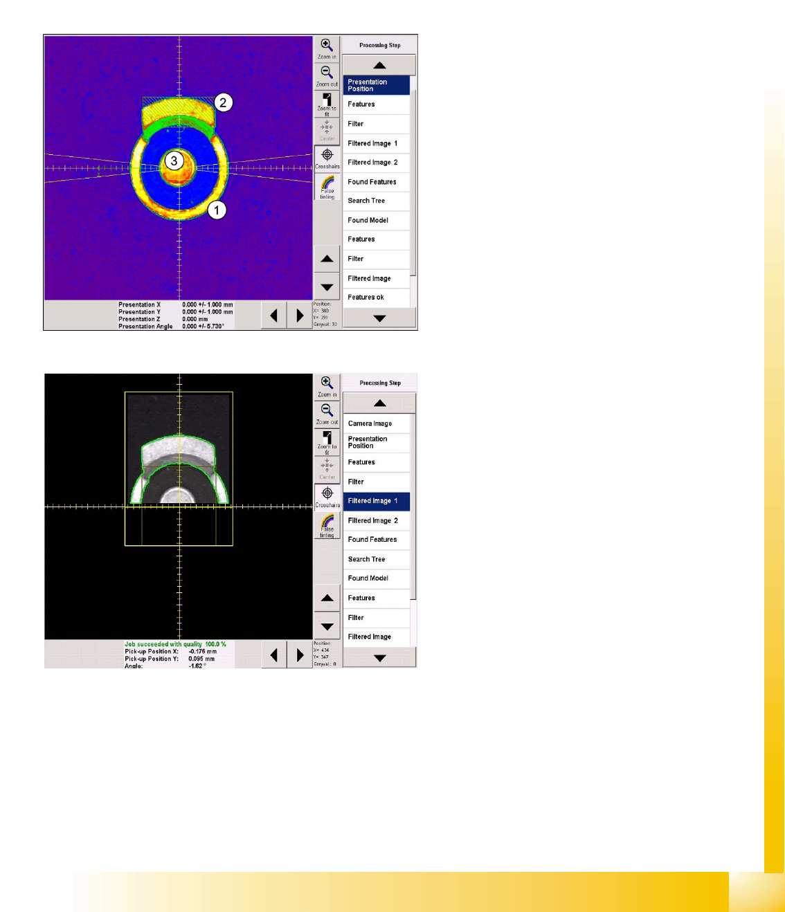
Recognition step Presentation position
This CS is programmed as a vertical cylinder (1).
The diameter is the outer diameter of the ring
(indicated by the green dotted line).
The first lead group is the metal flag pointing
upwards (2), programmed as a Blob.
The second lead group is the circular central lead
(3), programmed as a Ballcircle.
As usual, the presentation position (white dotted
cross), CO X/Y coordinates (green arrows) and
the permitted angle tolerance are entered here but
will not all be visible in the printout.
Recognition step Filter 1
The lead type Blob is a rectangle with dimensions
of 2.5 x 6.3 mm. This defines the lead center,
which is taken as the basis for the Blob lead (bright
shape) search region and forms the focus of this
shape.
The search region for the second lead group is
marked as a dark square in the evaluation image
for the first group.
Component Shapes
Specific Component Shapes Optical Recognition of Free Programmed COs
Student Guide SIPLACE Vision (Customer)
Component Shapes Edition 12/2008 EN
100
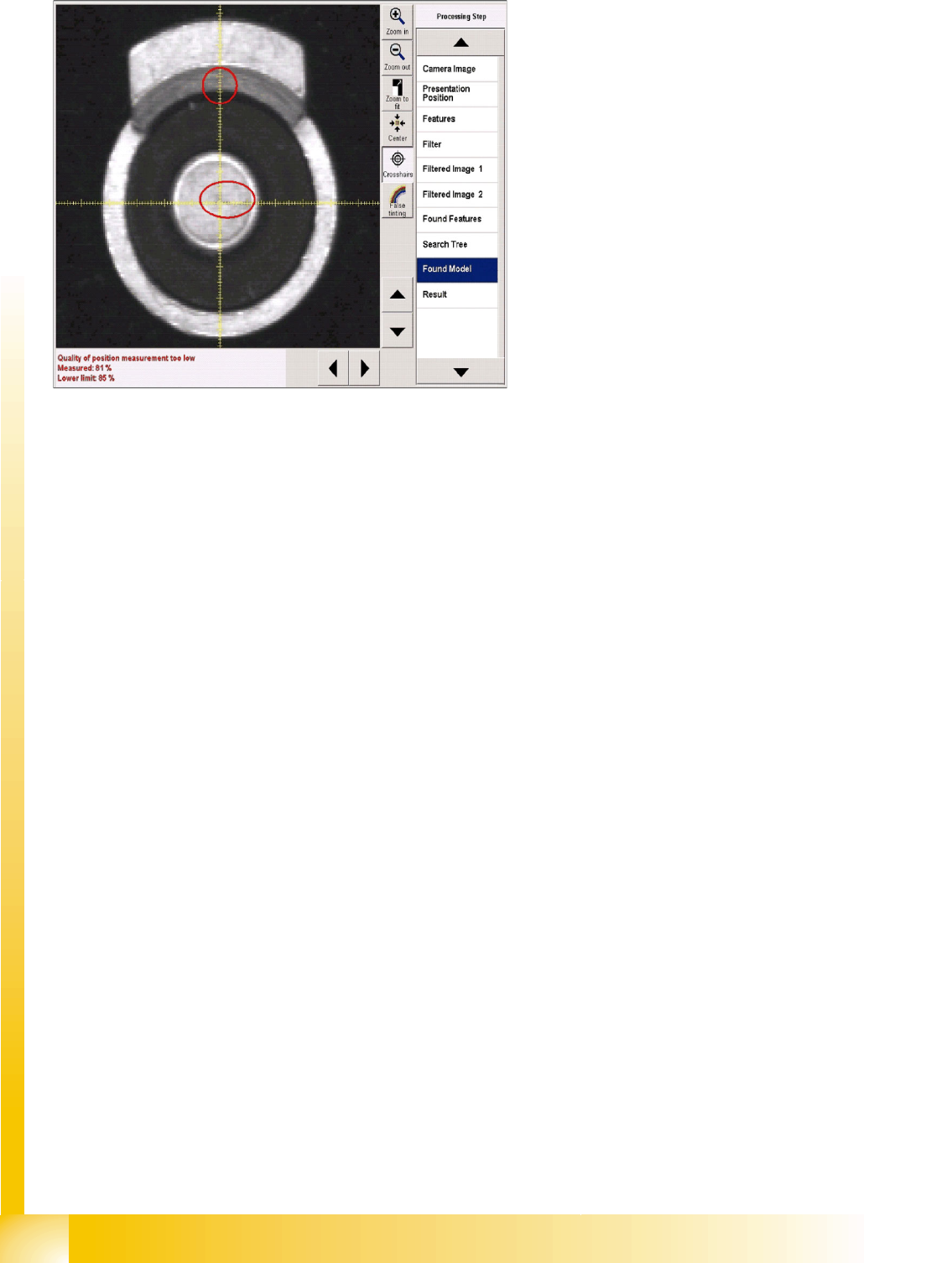
Error processing
If error messages are issued during the
recognition steps, the error reason will be
displayed in the results window, under the camera
image.
IN a corresponding recognition step, the
evaluation will be omitted (red rings) and the
steps for the subsequent component inspection
will not be available in the selection menu.

Component Shapes
SIPLACE Vision Image Export/Import New SIPLACE Vision Functions for 605 and 701 Station SW
Student Guide SIPLACE Vision (Customer)
Edition 12/2008 EN Component Shapes
101
5.4 New SIPLACE Vision Functions for 605 and 701 Station SW
Three new functions have been introduced for these 2 station software versions.
701/604.01: Export/import of the SIPLACE Vision images into a component shape description
including manipulation settings such as illumination and algorithms.
701: Robustness display for the teached component with the selected settings (also available in 605
SW at a later date)
605: Flux inspection of all component shape types for dipping before optical centering.
5.4.1 SIPLACE Vision Image Export/Import
In order to adopt modifications to the teached component shape, carried out in other systems, an import/
export function for SIPLACE Vision log files was implemented in SIPLACE Vision 701.
5.4.1.1 Export Function
The
Export Vision Data
option in the new SIPLACE
Vision
pull-down menu of the SIPLACE Vision
TeachStation creates an XML file including the data that were created by modifying the illumination or
the algorithms! This export function is not available at the placement station. Here, it is still sufficient to
save a SIPLACE Vision context file.
The SIPLACE Pro component shape export only exports the programmed standard data set without the
data that were created during teaching by means of modifying the illumination or the algorithms.
5.4.1.2 Import Function
This function is only available on the station with an active component camera.
Procedure:
X Provide the storage medium containing the XML file of the SIPLACE Vision TeachStation (result of
a SIPLACE Vision error analysis) in the station SW.
X In the component shape teach interface select the
Vision
und
Import Vision Data
pull-down menu
or the
Import Vision Data
menu button.
X Get the required component from the feeder in component shape teach mode.
X Select the
Import Vision Data
function and the required file on the storage medium.
X The programmer's sketch of the component shape will be displayed. Now it is necessary to test if the
selected settings really lead to a secure recognition of the components!
X If a secure component recognition is assured, quit the component shape teach menu and save the
data (including manipulated data such as illumination or algorithms if present) via
Save Data
to the
SIPLACE Pro computer.
NOTE: A "re-import" into SIPLACE Pro can only be carried out via the SIPLACE Vision
user interface of the station SW.
All SIPLACE Pro versions display an "incorrect XML format" if these files are directly re-imported
into SIPLACE Pro.
X For this reason it is helpful to use the same name for ...sensorXX.SVDMP and
...sensorxx.XML.