SIPLACE Vision Customer_en.pdf - 第53页
Component Shapes CHIP Component Shape Specific Component Shapes S tudent Guide SIPLACE Vision (Customer) Edition 12/2008 EN Component Shapes 53 About Example A: CHIP component is correctly positioned at the nozzle; histo…
Component Shapes
Specific Component Shapes CHIP Component Shape
Student Guide SIPLACE Vision (Customer)
Component Shapes Edition 12/2008 EN
52
Special features
The inspection mode is set as a default. This can not be changed, since the body dimensions also
need to be measured (Body Dimension Check), to avoid vertical placement due to upright/sideways
pickup. The body description tolerances should therefore be kept sufficiently low.
Joint datasets with ICOS data possible:In ICOS descriptions, a CO dimension check is only performed
if the lead width matches the body width. Check the tolerance values and reduce if necessary. CHIP
components, which have been programmed as PDC, can not be automatically assigned. In this case,
you will need to reprogram the CS with the leads.
Due to the very simple programming method, involving body size with attached wraparound leads, NO
component shape wizard is offered for CHIP component shapes.
SW extension: Lead length inspection can be programmed and used for CHIP component shapes from
SC 702.
Recognition of flipped components
A flipped CHIP component can be recognized with the so-called Face Down method and placement
of it then omitted, if this option is enabled in the CS programming function of SIPLACE Pro. Unless
you want to check all COs under this component shape for this pickup error, create an additional CS,
which can be selected for this option.
Recognition of flipped COs can be enabled or disabled in the geometry data menu. When using
ICOS systems, this option is trained at the station and the results stored in the SST camera file.
ICOS and SIPLACE Vision use the same measurement principles for this option.
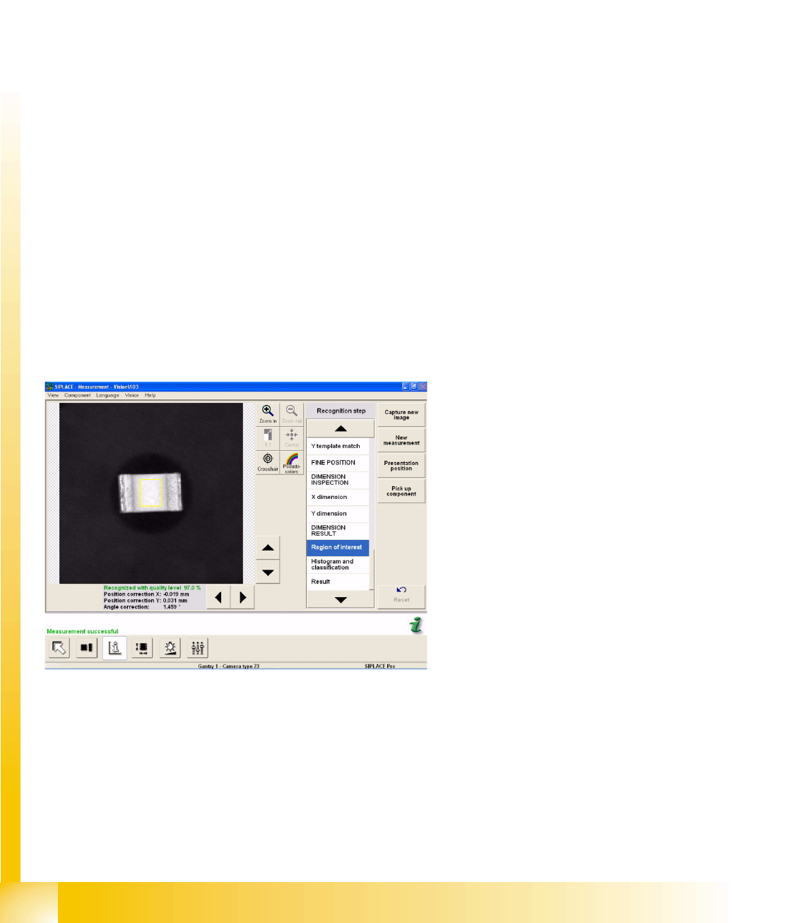
An additional measurement window is created around the center of the CHIP CO (Region of Interest,
for flipped recognition). Inside this window, all the brightness values greater than 127 will be
interpreted as CO bottom side (additional evaluation steps cover generation of a histogram and
classification). The brightness values below 127 are then interpreted as CO top side.
Example A:
CHIP component is correctly positioned at the
nozzle; during the recognition step Region of
Interest.
Component Shapes
CHIP Component Shape Specific Component Shapes
Student Guide SIPLACE Vision (Customer)
Edition 12/2008 EN Component Shapes
53
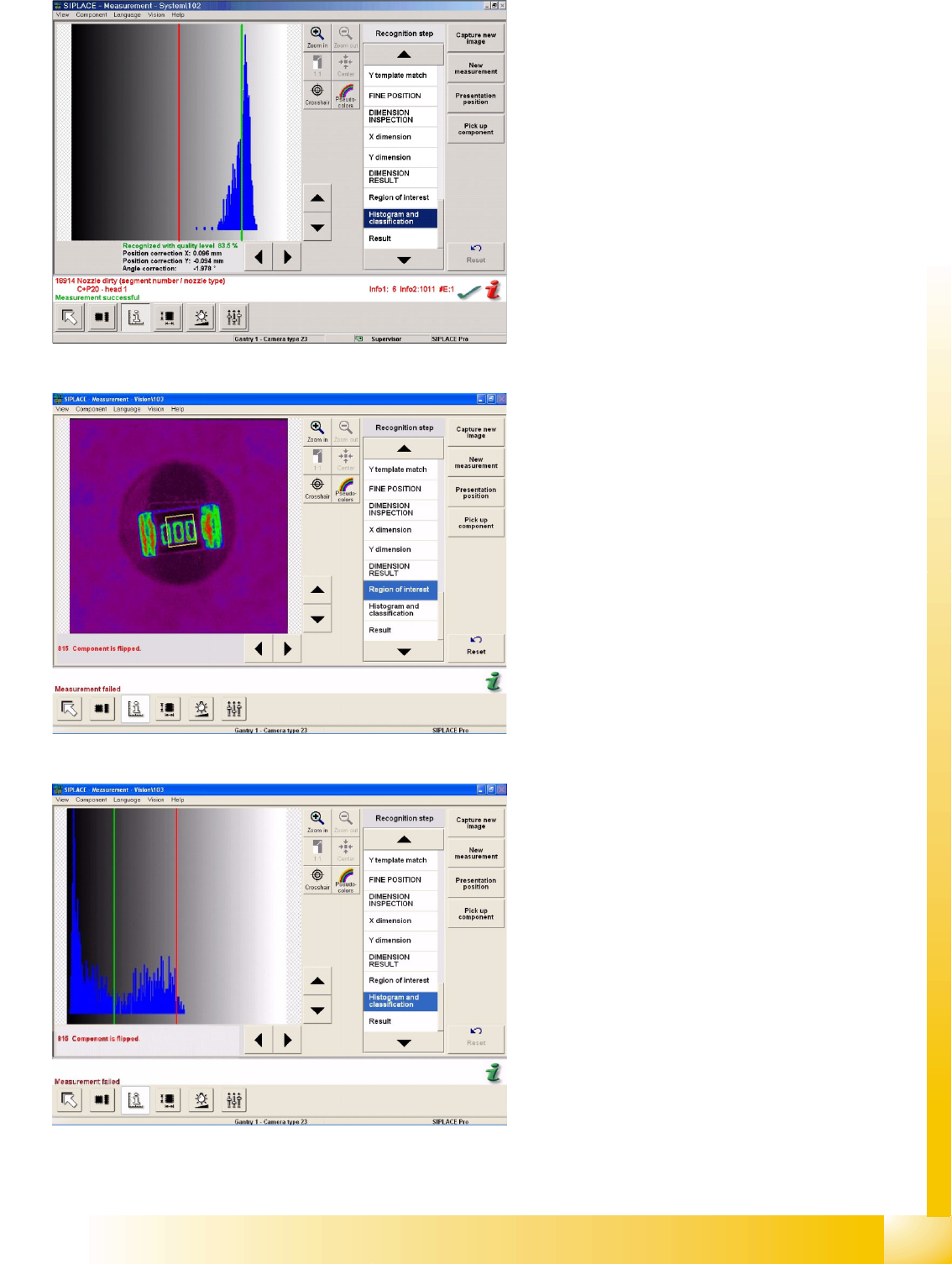
About Example A:
CHIP component is correctly positioned at the
nozzle; histogram and classification steps are
performed. The diagram shows the brightness
histogram i.e. the number of gray/white pixels.
Example B:
CHIP component is flipped and positioned at the
nozzle, during the recognition step Region of
Interest.
About Example B:
CHIP component is correctly positioned at the
nozzle; histogram and classification steps are
performed. The diagram shows the brightness
histogram of the CO label.
Component Shapes
Specific Component Shapes CHIP Component Shape
Student Guide SIPLACE Vision (Customer)
Component Shapes Edition 12/2008 EN
54
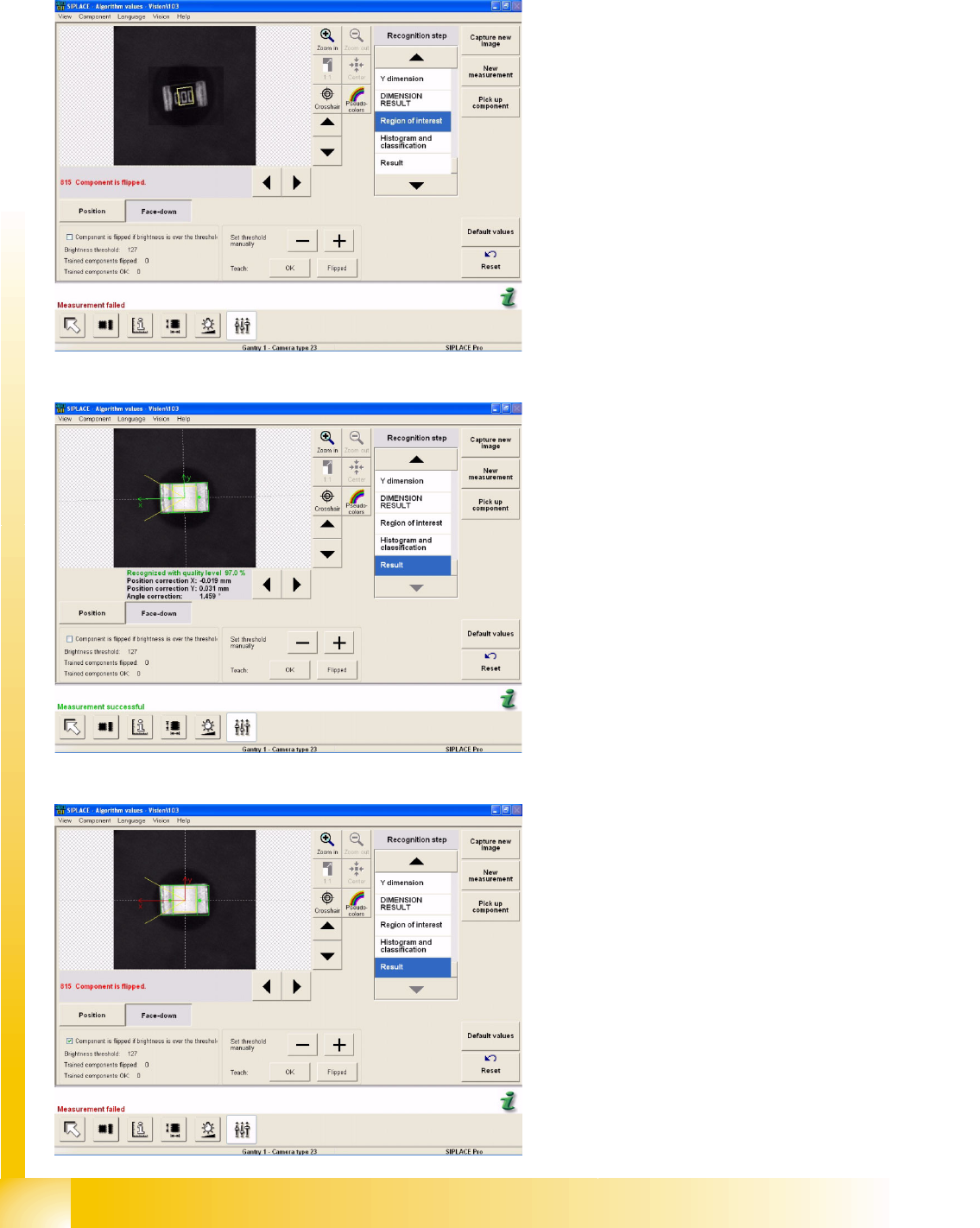
If this default setting (with a threshold of 127) is not adequate for reliable recognition, the required
threshold can be trained in the algorithm parameters of the SIPLACE Vision menu (CS measurement
modes in ICOS) Face Down.
Example C:
The diagram shows a flipped CHIP component.
The threshold has been raised to 154 and the
errors were recognized correctly.
Example D:
The diagram shows the teaching procedure for a
correctly recognized CHIP component. The
threshold has been increased to 126 and the
component was recognized correctly.
Example E:
Check this box to invert the evaluation. In this
case, all brightness values above the threshold will
now be interpreted as CO top side. The previous
teaching values will be reset.