SIPLACE Vision Customer_en.pdf - 第157页
SIPLACE Pro 3.0 Programming Interface for C omponent Shapes General Information about Automatic Conversion of Component Shapes Converting the Component Shape w ith LC Import from a UNIX/LI NUX S tudent Guide SIPLACE Visi…
SIPLACE Pro 3.0 Programming Interface for Component Shapes
Component Shape Import and Data Conversion for SIPLACE Vision Body Colors Codes for Changes to Component Shapes in SIPLACE Vision
Student Guide SIPLACE Vision (Customer)
SIPLACE Pro 3.0 Programming Interface for Component Shapes Edition 12/2008 EN
156
7.1.2 Body Colors Codes for Changes to Component Shapes in SIPLACE Vision
The body color of the component shape is an excellent way of clearly displaying the changes in the
customer's geometric database, without the need to open component shape details.
The changes represented by the colors are explained below:
To make CS maintenance clearer, this color-coding can and should be supplemented with explanatory
comments about the component shapes or change programming (right-click with the mouse on the CS
number).
The body colors can be used for placement information or assistance e.g. as follows.
7.1.3 General Information about Automatic Conversion of Component Shapes
Please observe the following shape-specific instructions:
BareDies: If the CS is not a real BareDie, you will need to teach it for the illumination. These cases
include PDC programming of chips, shields and special components.
You will also need templates for the classification and teaching.
ECV: Since these are automatically classified as Moulded, you need to check their type
classification. Body and lead types must be changed.
Socket: This component shape is classified as QFP, if the rectangular or square Socket points
outwards.
Connector: Double row connectors are classified as SO types.
Shields: Shields are classified as QFP, if they have been programmed for ICOS, with rectangular or
square virtual lead arrangements.
They are classified as BGA, if balls have been programmed for ICOS.
Separate group and lead data storage needs to be enabled in each case and corner/polygon circle
programming performed.
If there are no components available, the comments may help with the classification process.
Red: The component shape needs to be checked on a real element, as the data are not
suitable for SIPLACE Vision in this form and have been replaced by new component
shapes (see additional comments or change programming).
Green: The component shape has been successfully checked or trained on a real component.
Blue: The component shape was changed to Requires separate group description and
modifications have been made to the programming in SIPLACE Vision.
Orange: The ICOS dataset has been modified for centering in SIPLACE Vision.
Violet: The component shape still needs to be checked and trained on a real component.
Red Poled component! This makes a sight check by the line personnel easier to perform, as this is
easily seen.
Blue Separate group descriptions are required for ICOS and SIPLACE Vision.
Yellow Tantal component which should be manually removed by a pickup error
ECV capacitors which are pole-dependent.
Orange CHIP capacitor
Light blue CHIP resistor
Brown Connector with connect-through contacts and centering pins (through hole pin)
Violet Special components such as real bare dies
SIPLACE Pro 3.0 Programming Interface for Component Shapes
General Information about Automatic Conversion of Component Shapes Converting the Component Shape with LC Import from a UNIX/LINUX
Student Guide SIPLACE Vision (Customer)
Edition 12/2008 EN SIPLACE Pro 3.0 Programming Interface for Component Shapes
157
7.2 Converting the Component Shape with LC Import from a
UNIX/LINUX Line Computer
Machines from previous series such as F-Series or S20/S23/S25/S27HM/HS50/HS60 lines could be
controlled by a UNIX or LINUX line computer. New machines require an LC import of the GS database
from the line computer.
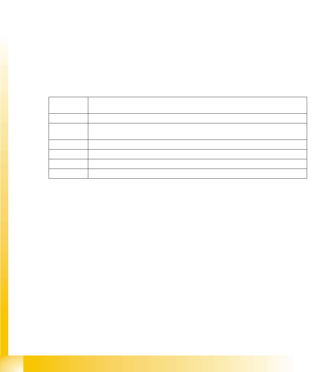
Select the menu LCU Import Wizard under Tools.
Use the browser to select the required master data
inventory from the network (from which the line
computer data (e.g. component shapes) are to be
imported). Specify the target directory in the
window shown. The selection window will display
the contents of the CS import directory and
individual component shapes can be selected.
The same import procedure can be used for
components and boards.
The messages generated during LC import can be
stored as an XML file, for subsequent processing
or documentation. Just right-click with the mouse
in the message field and then specify the path and
file name.
NOTE: Differences between SIPLACE Pro and LC CS programming!
The alignment of the lead group with 0° was Horizontal to the right in the line computer.
In SIPLACE Pro it has been redefined as Upward .
The line computer programs the ball radius, while SIPLACE Pro programs the ball diameter.
The CS comments field (50 characters) also has a conversion trick entry, in which manual
settings or other special details can be recorded.
SIPLACE Pro 3.0 Programming Interface for Component Shapes
Converting the Component Shape with LC Import from a UNIX/LINUX Line Computer Converting the Component Shape Type
Student Guide SIPLACE Vision (Customer)
SIPLACE Pro 3.0 Programming Interface for Component Shapes Edition 12/2008 EN
158
7.2.1 Converting the Component Shape Type
SIPLACE Vision (or SV) requires you to define a body shape, component type and lead type.
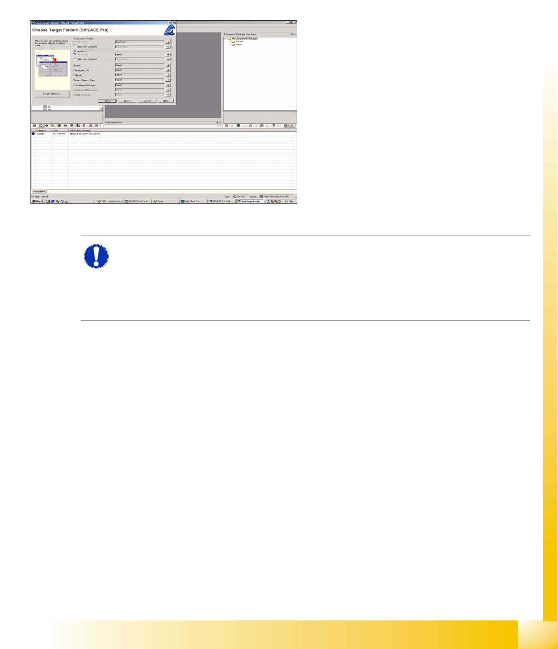
Program Start
Programming desk
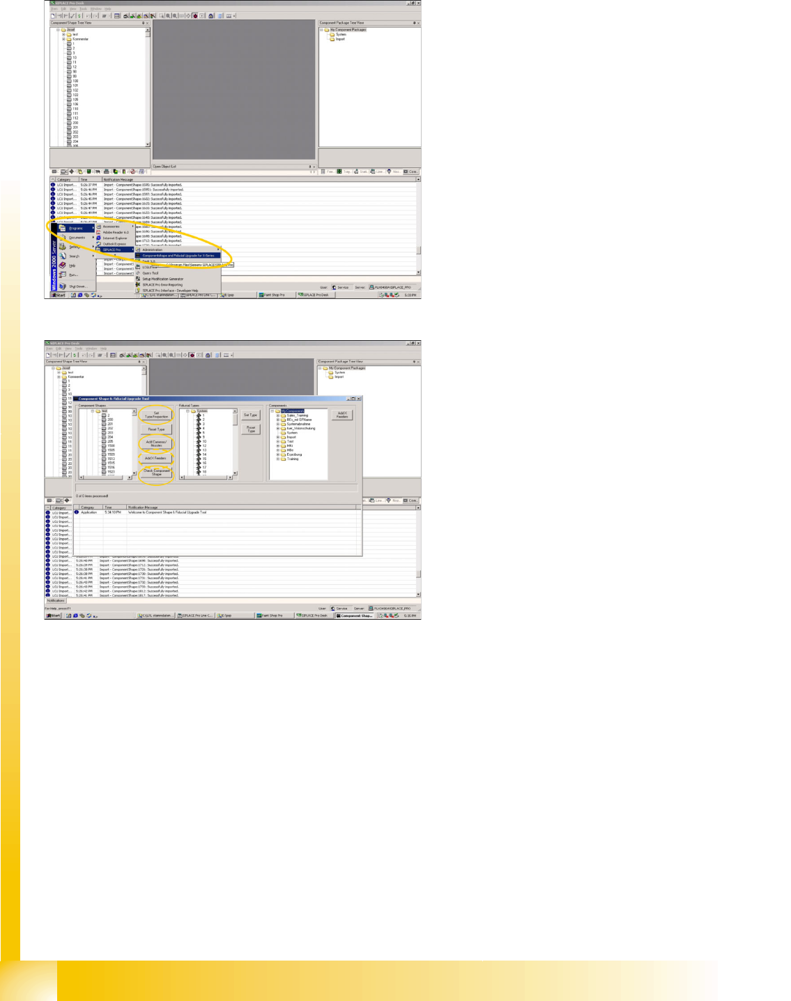
The first conversion refers to the component
type and the CS inspection mode.
This is followed by Check Component Shape,
which involves checking the lead type and the
allocation of the component type.
The new - digital - camera types can be added
in the Add Cameras/Nozzles menu.
If the new X machines are to be used with X
feeder tables (required for C&P20 heads),
enable the Add X Feeders menu.
After each of these steps (LC import/conversion
type/Inspection) check the report lists for any
errors or warnings. Changes to the individual
component shapes in the CS database should be
documented in a suitable report or printout.