SIPLACE Vision Customer_en.pdf - 第108页
Component Shapes New SIPLACE Vision Functions for 605 and 701 St ation SW SIPLACE Vision Robustness Display S tudent Guide SIPLACE V ision (Customer) Component Shapes Edition 12/2008 EN 108 5-12: FeatureSize test As can …
Component Shapes
SIPLACE Vision Robustness Display New SIPLACE Vision Functions for 605 and 701 Station SW
Student Guide SIPLACE Vision (Customer)
Edition 12/2008 EN Component Shapes
107
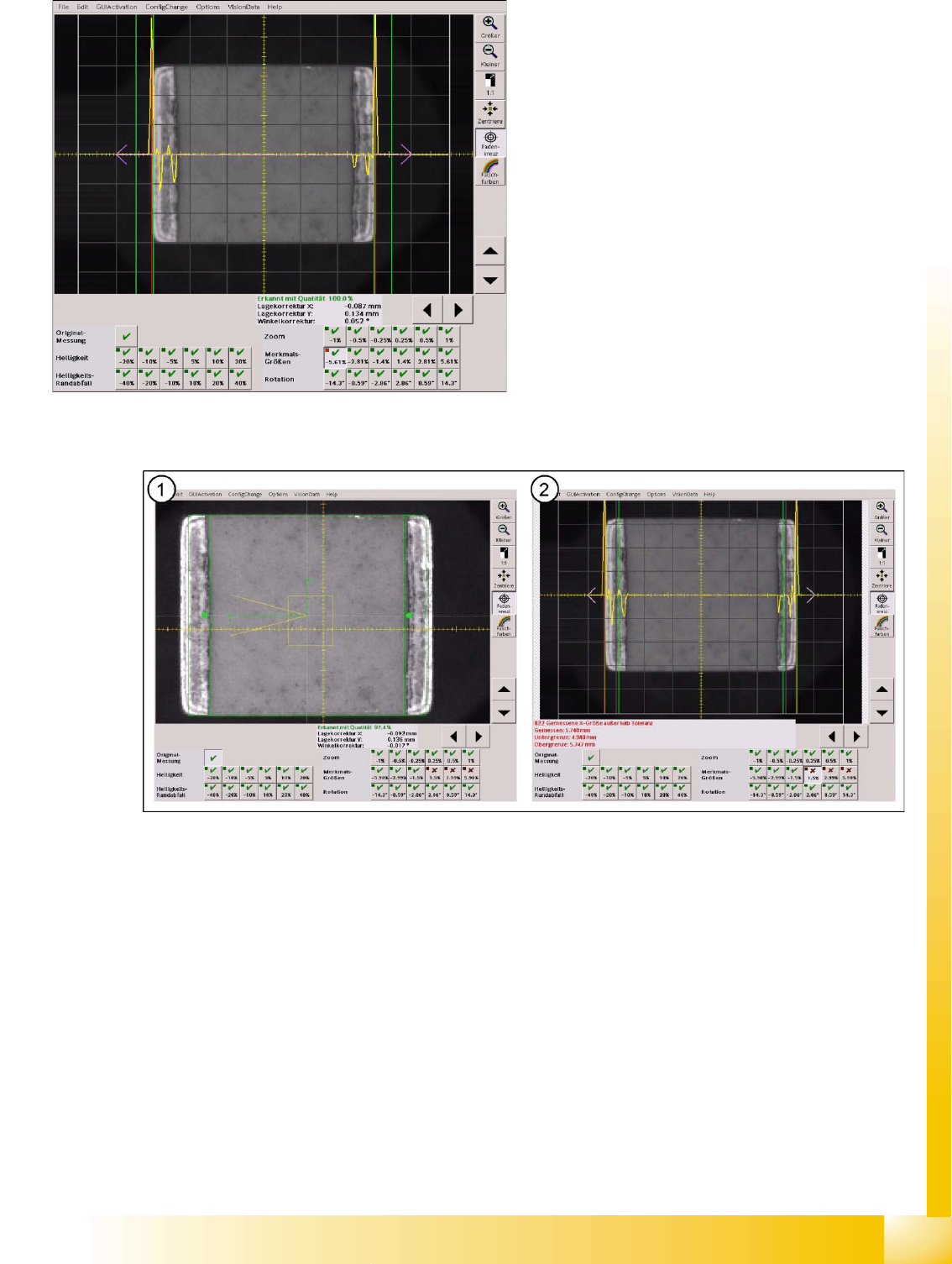
The opposite error situation, when the dimensions selected are too small:
5-11: Size programming error in the original result and as an effect of the "size check"
These robustness size checks applied to component shape types with leads show possible small
deviations of the feature geometries.
5-10: Corrected reduced component size X dimension check
The shape edge is now found within the 0.4 mm
tolerance in inspection step X dimension.
Component Shapes
New SIPLACE Vision Functions for 605 and 701 Station SW SIPLACE Vision Robustness Display
Student Guide SIPLACE Vision (Customer)
Component Shapes Edition 12/2008 EN
108
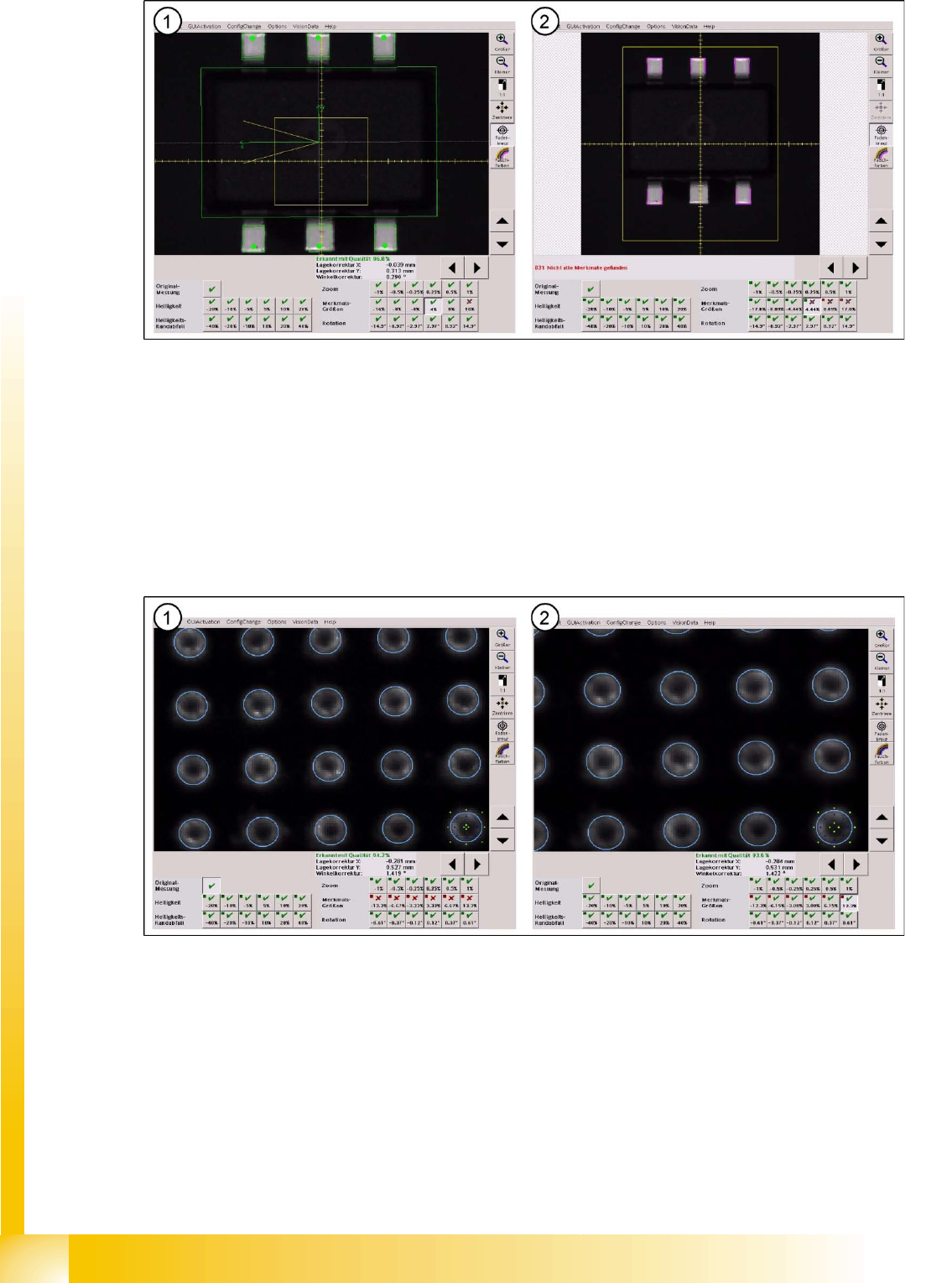
5-12: FeatureSize test
As can be seen in this zoomed view, the lower central lead is a bit too big. With an 8% zoom of the
component shape, image filter size and tolerance don't suffice to detect this lower central lead.
Zoom factors are adapted when the geometry is changed, which can be seen when comparing these
two displays.
The solution for detecting this lead with its oversized width is to increase the lead width from 0.32 mm to
0.35 mm and to reset the tolerance to 20%.
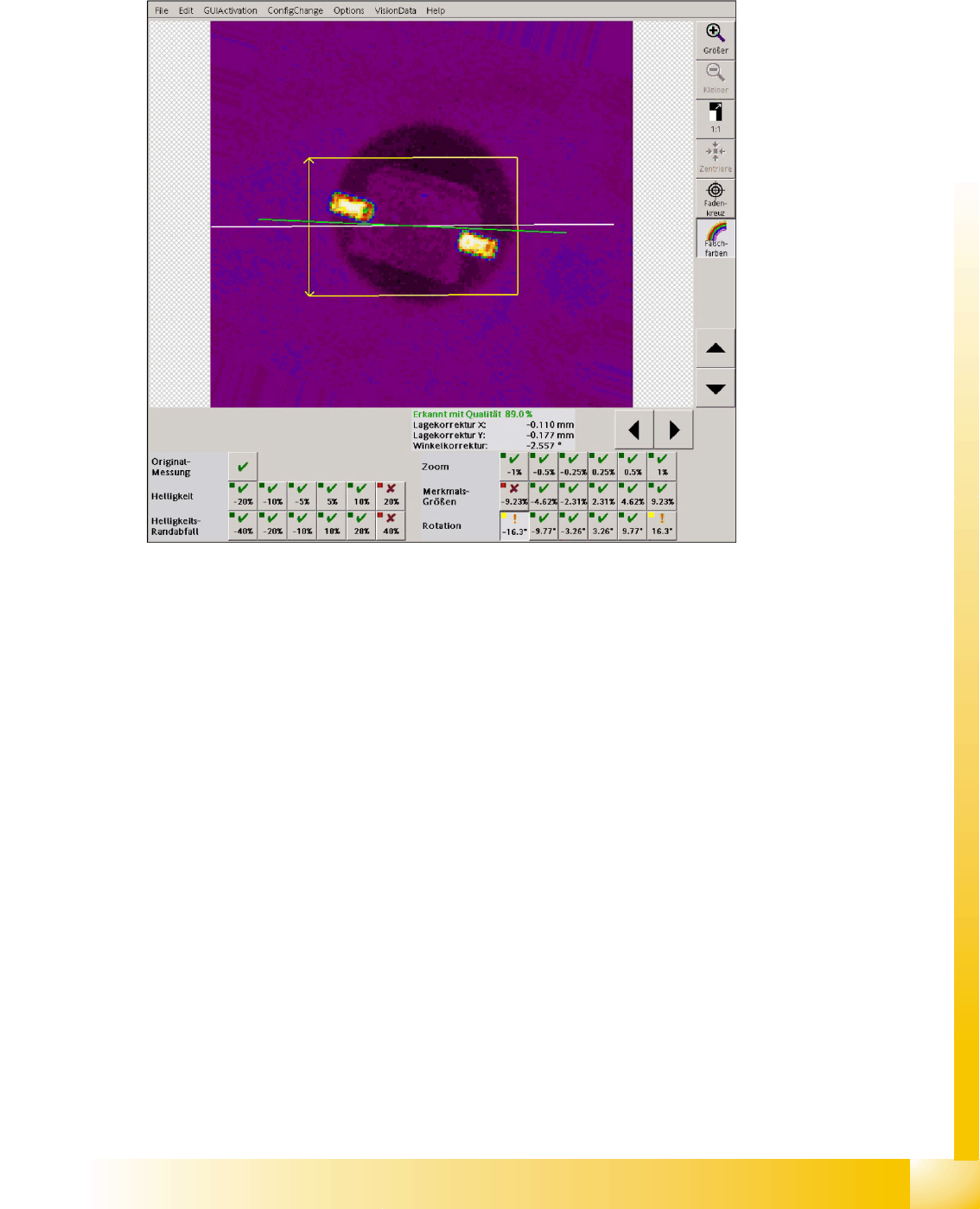
Looking at the following BGA example it is not possible to see doubtlessly that the ball diameter is
programmed too small in the original optical centering (only visible with higher zoom).
5-13: Ball diameter
Legend
1. The ball diameter, which is programmed with 0.6 mm in this case, only fits in the original
measurement.
2. A correction to 0.65 mm ball diameter supplies correct results for all 6 feature size measurements.
Component Shapes
SIPLACE Vision Robustness Display New SIPLACE Vision Functions for 605 and 701 Station SW
Student Guide SIPLACE Vision (Customer)
Edition 12/2008 EN Component Shapes
109
5.4.2.6 Rotation
In the following 6 measurement steps the component image is rotated electronically and a detection is
carried out. It is checked if the measurement methods can detect these rotated component images with
the existing algorithms or filters.
5-14: Angle measurement in the robustness test
The angle measurement fails in the fine angle measurement step if the camera image was rotated to
16°. The measurement returns a result which, however, doesn't reflect the actual angle position which
is near the programmed tolerance minimum.
Attention: A SOD323 component with this angle position would be incorrectly placed.