SIPLACE Vision Customer_en.pdf - 第30页
User Interface Programming Interface for Illumination Adjustment Station Interface for Teaching Component Shapes S tudent Guide SIPLACE V ision (Customer) User Interface Edition 12/2008 EN 30 4.8 Programming Interface fo…
User Interface
Station Interface for Teaching Component Shapes Setting the Illumination
Student Guide SIPLACE Vision (Customer)
Edition 12/2008 EN User Interface
29
When using ceramic carriers with gold contacts, switch off steep illumination levelshere and test with
the intensity of a flat 90° (possibly also with 60°) illumination level. The gold lead will be shown darker
than the white carrier so also enable the setting Feature is dark for wraparounds!
Socket shapes may contain two different leads, over one another. In this case, we recommend
setting low intensity for the flat illumination level and a higher intensity for the steep illumination level.
When using a light-colored component shape with leads, reducing the flat illumination applied will
make the body of the component appear darker. Shining leads only need low steep illumination to
make them clearly visible, see gradient profile.
Note: The illumination may overmodulate if large parts of the CS properties become white in the pseudo-
colors view. Make sure you avoid this overmodulation!.
Columns CCGA Steep inside 60, steep outside 60, middle 30° 0, middle 60° 0,
flat 0, flat corners 0.
Blob Nonstandard Steep inside 75, steep outside 75, middle 30° 30, middle 60° 0,
flat 0, flat corners 0.
Corners Shields
Nonstandard
Steep inside 30, steep outside 30, middle 30° 75, middle 60° 60,
flat 0, flat corners 0.
Centering pins Nonstandard / socket /
connector
No optical recognition of this feature
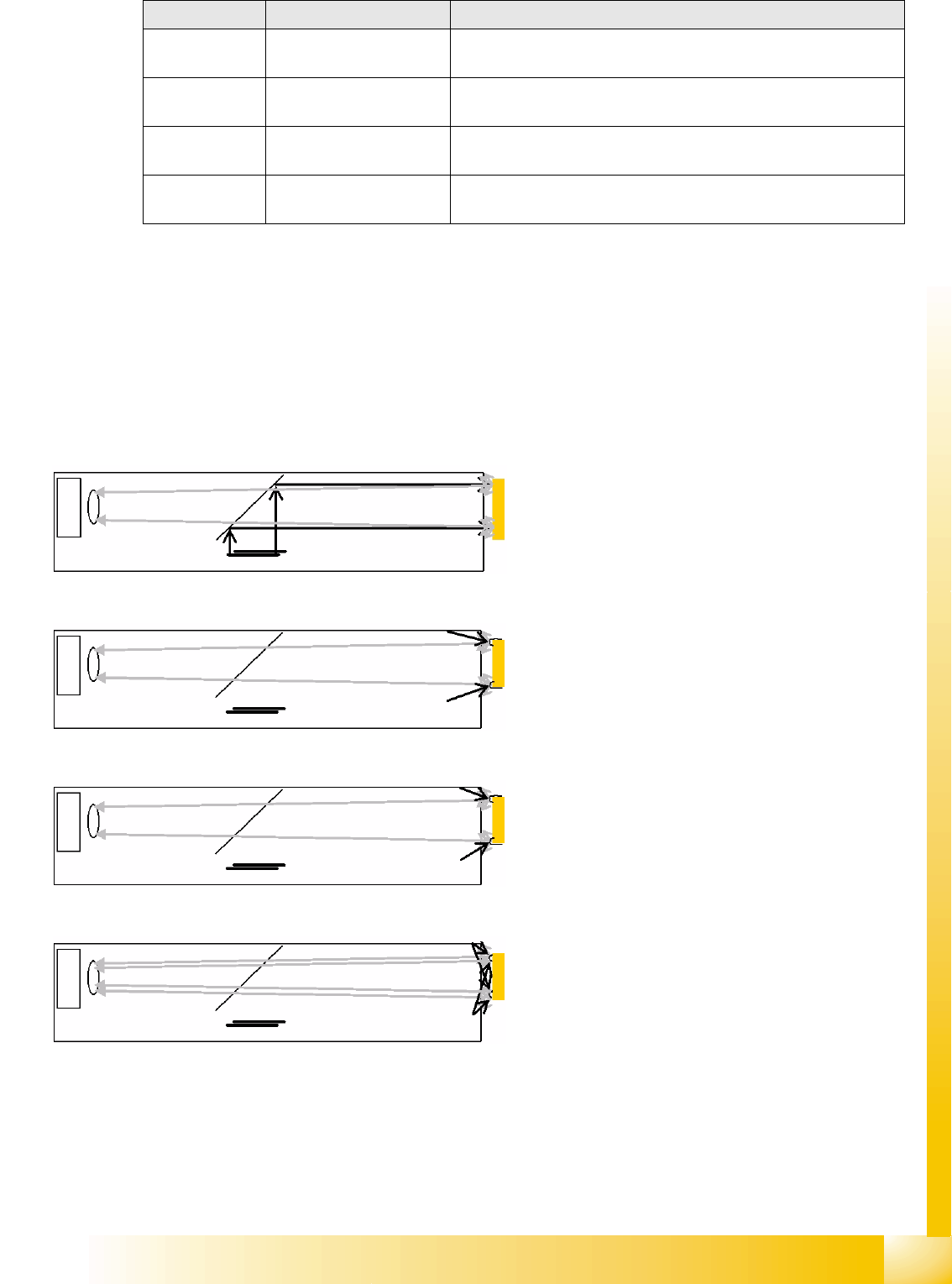
Lead shape Typical CO Example of standard illumination values for TWIN
The steep illumination level is primarily used for
displaying mirrored surfaces. This is ideal for
measuring shapes such as BareDies.
The middle illumination level 30° is used for
displaying curved leads. This is ideal for
measuring shapes such as PLCCs.
The middle illumination level 60° is used for
displaying curved and hemispherical leads. This is
ideal for measuring shapes such as BGAs.
The flat illumination level 90° is used for displaying
curved and hemispherical leads. This is ideal for
measuring shapes such as BGAs and
semicircular, curved leads.
User Interface
Programming Interface for Illumination Adjustment Station Interface for Teaching Component Shapes
Student Guide SIPLACE Vision (Customer)
User Interface Edition 12/2008 EN
30
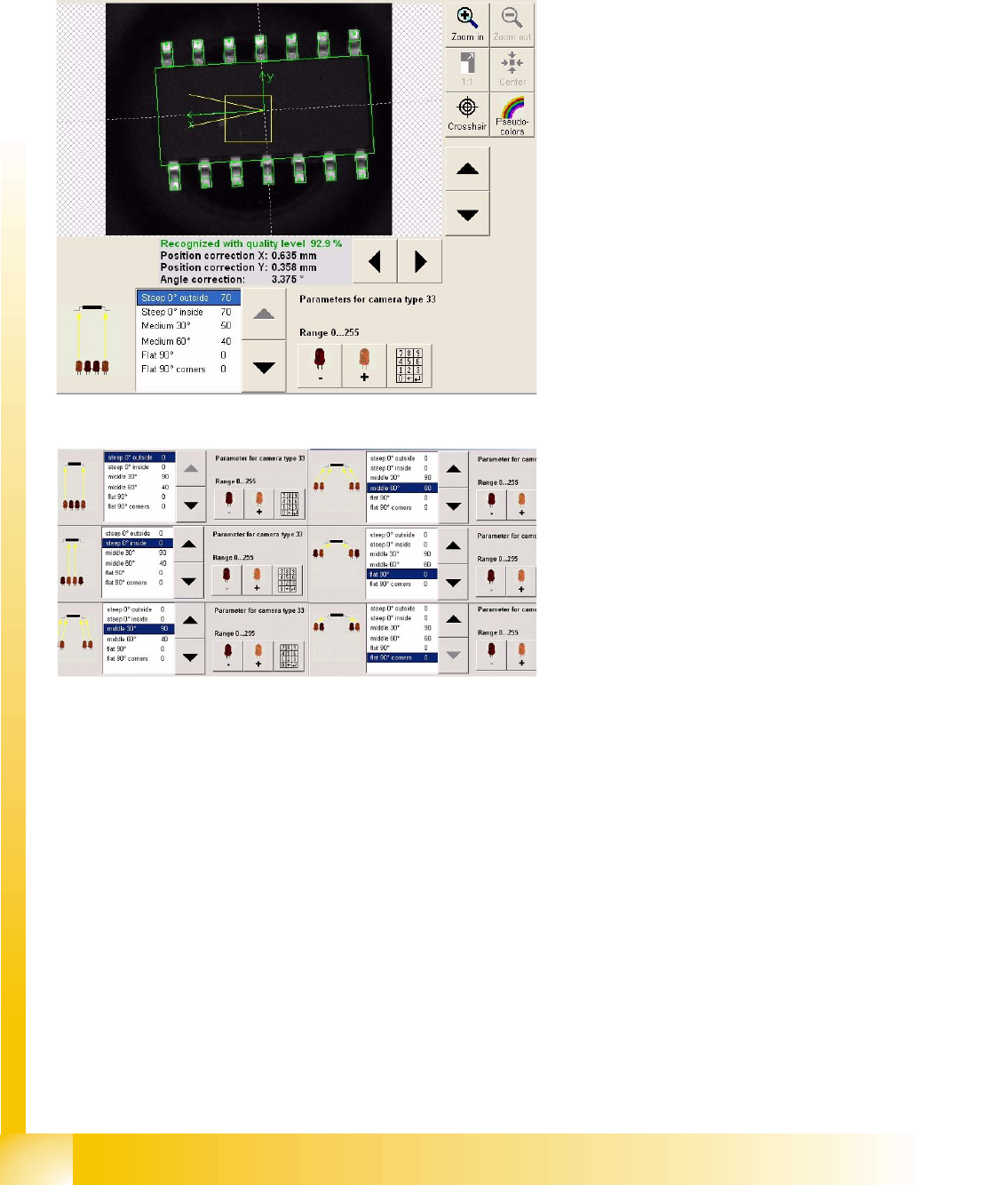
4.8 Programming Interface for Illumination Adjustment
Each component type definition sets the optimum standard illumination type for that particular
component shape. However, there are some component surfaces, which can not be adequately
illuminated with these standard values. In these cases, you will need to adjust the illumination at the
station.
Adjusting the illumination
Any suitable recognition step can be selected for
illumination adjustment.
In the example shown, the middle illumination
level was selected. The indicated illumination
angle is flatter than in the diagram above.
A new image recording is automatically made after
each alteration, enabling the user to evaluate the
illumination during adjustment.
Illumination levels
The adjacent diagram shows the regions for
selection the 6 different illumination levels.
Use the arrow buttons (up/down) to select the
required level.
Use the relevant LED symbol +/- to adjust the
intensity of each illumination level (256 steps).
User Interface
Station Interface for Teaching Component Shapes Setting the Algorithms
Student Guide SIPLACE Vision (Customer)
Edition 12/2008 EN User Interface
31
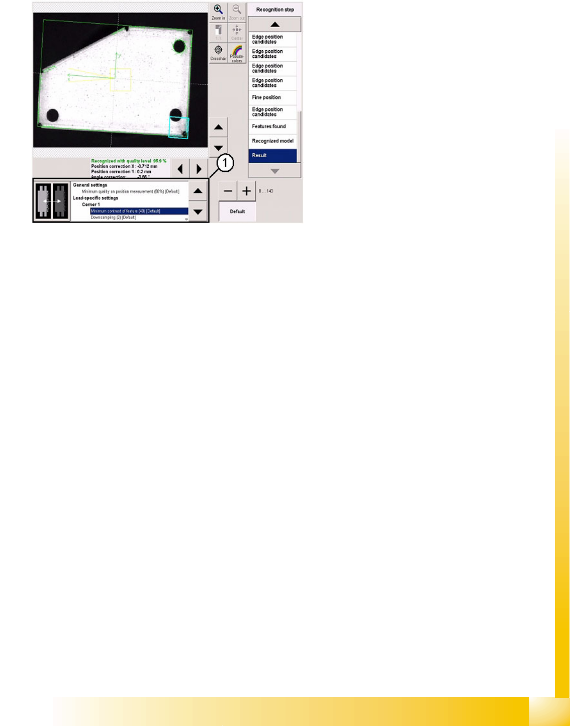
4.9 Setting the Algorithms
Use the list on the right to select and adjust the
individual measurement steps.
Settings are only possible here in exceptional
cases e.g. when analyzing images with inverted
colors.
1. The algorithm thresholds can be set in the
window shown. The recognition steps can be
altered independently of these.
The algorithm thresholds apply for the entire
position recognition function and for the
respective group descriptions.