SIPLACE Vision Customer_en.pdf - 第205页
在线预览 SIPLACE Vision Customer_en.pdf PDF 文档。
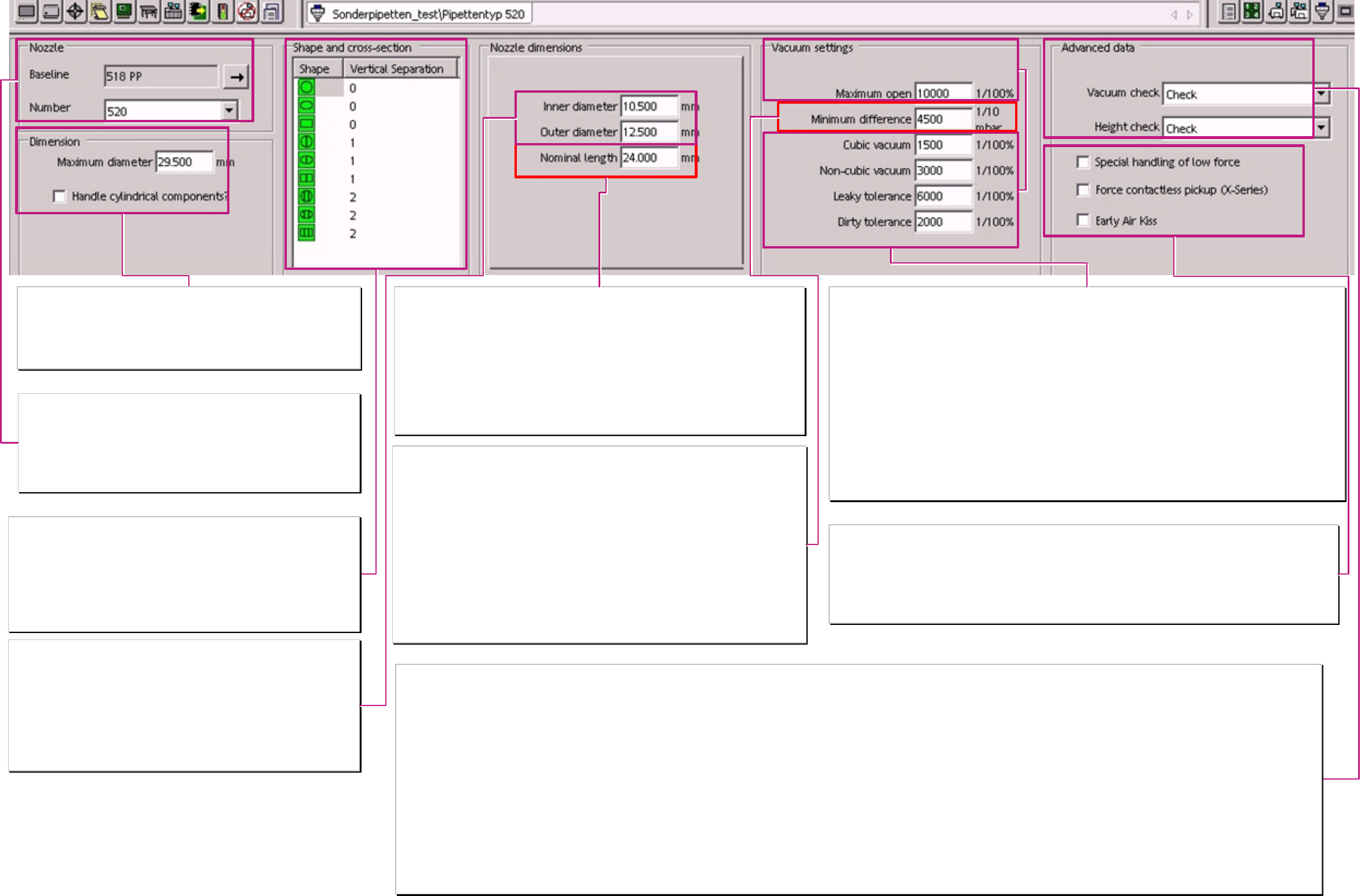
Nozzle
Base(nozzle)line
If a 5xx nozzle is to create the ‚Base nozzle’ have to be taken from this series too.
As a work around the programming values of another series could be written into
each single programming window.
Number(of nozzle)
this is the type number for the customized nozzle at SIPLACE Pro or station.
Nozzle programming for customized Nozzles
Dimension (Nozzle)
With this maximal (nozzle) diameter the definition is done for the SIPLACE Pro
Optimizer. It defines if the nozzle 5xx fit to the nozzle magazines or not.
Handle cylindrical components?
With this flag are set the functions for the handling methods of MELF components
(e.g. Pickup position correction OFF).
Shape and cross section ( of top of the nozzle)
Shape
This shape simplifies the programming at the SIPLACE Pro desk.
This shape (&dimensions) is NOT used for nozzle scanning. It is for a better
estimation of the programmer at SIPLACE Pro for the placement process.
Vertical separation
this programming is also for a better estimation on the placement process.
The programmer could recognize if a tiny component could be sucked into the
nozzle.
Nominal length
This value depends on the setting of the parameter ‚Height check’! Is one of the following setting
selected:
>’Disabled’ The nozzle length is NOT measured during the reference run. Therefore, the
programmed length of the nozzle is used for the Z-height during positioning
gantry axes respectively for the Z-height at pickup, centering, and placement.
> ’Enabled’ The nozzle length is measured during the reference run. The measured nozzle
length is used at placement process. The programmed value could be longer
than the real nozzle is.
> ’Check’ The nozzle length is measured during the reference run. The measured nozzle
length have to fit to the programmed nozzle length. This measured and
checked value is used for pickup -, centering -, and placement height.
Nozzle dimensions
Round Nozzles show here only diameter dimensions. Other shapes of Nozzles
(oval/ rectangular) show here length and width dimensions too.
The Programming and Darstellung is only for the orientation of the SIPLACE Pro
Programmers.
Inner length defines the whole (longest) length of the sucking opening.
Outer length defines the real outer edge of the nozzle (in X-direction).
Beneath the nominal length parameter.
Inner width defines the whole width of the sucking opening.
Outer width defines the real outer edge of the nozzle (in Y-direction).
Vacuum settings
These values depend on the nozzle type. The definitions of the single values change also because of the placement head
type:
Max. Vacuum open here is (except at C&P20) entered with 10000 (1/10 mbar) the theoretical maximum vacuum.
At C&P20 is here the ’maximum’ value(diference) for Vacuum open for this specific nozzle programmed.
This defines the limit to the 0mbar controller state for environment pressure.
Cubic Vacuum At the C&P placement heads not used.
At TIWN / P&P-heads the component presence is checked with this percentage value with a vacuum
test.
(This value is tinier than ‚Vacuum Not cubic’)
NON cubic Vacuum At C&P12/6 for the vacuum based component presence check used.
Not used at C&P20.
At TWIN/P&P the check of the vacuum value for this threshold at the pickup moment starts Z-axis
upwards after pickup.
Leaky tolerance for Percentage value of programmed air kiss level at the placement moment for the TWIN / P&P head.
An air kiss value at this percentage threshold of the programmed Air kiss at the placement moment
starts the Z-axis upwards after placement. For C&P-heads this value is not used.
Dirty tolerance This programming is not used for any placement head.
Minimum Difference
here is the typical vacuum difference between open and closed state for the nozzle opening
programmed.
The Vacuum measurement for nozzle recognition is generally executed at reference run and this is
also done for the C&P20 head and for nozzles with vacuum difference of 10mbar or more.
> ’Disabled’ here you could enter 0 mbar; e.g. at grippers (590 nozzles) which have no vacuum
suction opening. No vacuum measurement is executed at reference run and at
placement, no component presence check (based on vacuum) is tested.
> ’Enabled’ here is a minimum vacuum difference value programmed. At reference run the
measurement result is surely above this limit. The measurement result is NOT taken for
calculation of the vacuum check based - component presence check.
> ’Check’ this minimum, programmed value is surely exceeded at the vacuum check in reference
run. Otherwise the nozzle is displayed for error ‚Vacuum difference too tiny’.
Only here is a component presence check on vacuum test base possible after pickup or
before placement.
Advanced Data
Here in this extension, ‘Advanced’ Data, is the kind of placement head check for the reference run set.
Vacuum check
The kind of vacuum check of the nozzle is set, which is the base for the component presence recognition with vacuum check at the placement sequence.
(at C&P20 heads a vacuum check is executed at reference run but no component presence check based on a vacuum test.)
> ’Disabled. No vacuum check executed during the reference run or at SITEST. Therefore, it is also no comp. presence check possible based on vacuum tests during placement.
> ‘Enabled’ A vacuum check is executed during the reference run or at SITEST. The measured value is accepted like measured and from this result the ‘Vacuum NOT cubic’ is taken. BUT NO component presence
is possible, because the measured Vacuum diference could be too tiny for component presence check!!!
> ’Check’ The vacuum check is executed during the reference run. The measured value have to exceed the ‚Minimum difference’ for the vacuum difference open and closed. Otherwise, an error message is
displayed and the nozzle has to be changed.
Height check
The machine uses the measured nozzle length for nozzle type - and for height recognition of placement head.
> ‘Disabled’ This could be programmed for grippers or nozzles where a part of the nozzle move into the component opening (connector) The programmed length of the nozzle has to be as long as it works on the
component.
> ‘Enabled’ here a very long nozzle length could be programmed which guarantee that the nozzle do not ouch too hard on the transport rail at height reference run. The system accepts the nozzle length for placement
like measured.
> ‘Check’ The nozzle length and the head height is measured during reference run when the nozzles touch onto the transport rail. The nozzle length result may deviate about 0.4mm (C&P20 0,2mm) from
programmed value.
Handling setting
Special handling of low force Here the setting done for placements with lowest placement force of 0.5-0.9N of the TWIN-
head. (This is a special construction (SOKO) for a special adjusted TWIN-placement head).
It is also used for 0402mm(01005) ‚special’ placement with 905 nozzles on D1/2/4.
Force contactless pickup (X-series) At C&P-heads of the X-series such a nozzle would pick up all kind of components
contactless.
early air kiss Not to program for any special nozzel on any kind of placement heads
A programing overview about process reliability Editon for SIPLACE Pro 5.0 extended for 5.2

All names identified by ® are registered trademarks of the Siemens AG. The remaining trademarks in this publication may be trademarks
whose use by third parties for their own purposes could violate the rights of the owner.
We have reviewed t he contents of this publication to ensure consistency with the hardware and software described. Since variance cannot
be precluded entirely, we cannot guarantee full consistency. However, the information in this publication is reviewed regularly and any
necessary connections are included in subsequent editions.
Copyright © Siemens AG 2008 Technical data subject to change
Siemens AG Item no.: 00194934-05
Industry Sector
Electronics Assembly Systems
Rupert-Mayer-Strasse 44
81379 Muenchen
Germany
www.siplace.com